


37
XM
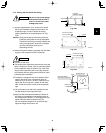
3-12. Checking the Drainage
After wiring and drain piping are completed, use the following pro-
cedure to check that the water will drain smoothly. For this, pre-
pare a bucket and wiping cloth to catch and wipe up spilled water.
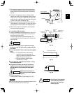
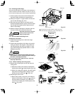
(1) Connect power to the power terminal board (R, S
terminals) inside the electrical component box.
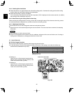
(2) Slowly pour approx. 0.13 gal of water into the drain
pan to check drainage. (Fig. 3-37)
(3) Short the check pin (CHK) on the indoor control
board and operate the drain pump. Check the water
flow through the transparent drain pipe and see if
there is any leakage.
(4) When the check of drainage is complete, open the
check pin (CHK) and remount the tube cover.
CAUTION
Be careful since the fan will start
when you short the pin on the
indoor control board.
Water drain
Drain pan outlet
Water
(Approx. 0.13 gal)
Plastic container
for water intake
Over
3-15/16"
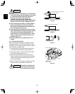
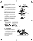
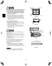
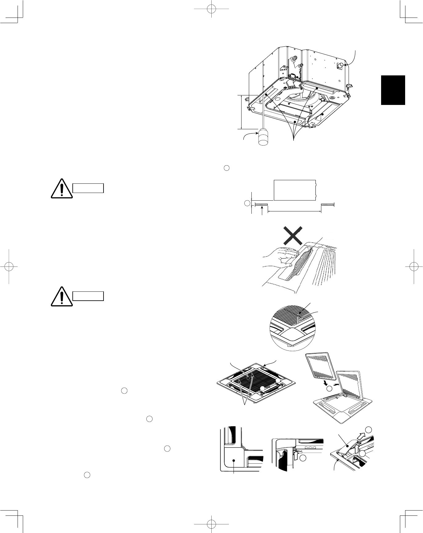
3-13. How to Install the Ceiling Panel
Checking the unit position
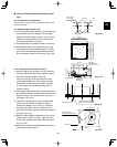
(1) Check that the ceiling hole is within this range:
23-5/8" × 23-5/8"
(2) Confirm that the position of the indoor unit and the
ceiling as shown in the diagram. If the positions of
the ceiling surface and unit do not match, air leak-
age, water leakage, flap operation failure, or other
problems may occur.
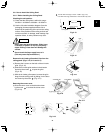
●
Never place the panel face-down. Either hang it verti-
cally or place it on top of a projecting object. Placing it
face-down will damage the surface.
●
Do not touch the flap or apply force to it. (This may
cause flap malfunction.)
A
must be within the range of 33/64" to 45/64". (Fig. 3-38)
If not within this range, malfunction or other trouble may occur.
CAUTION
A
Main unit
Ceiling side
Ceiling opening
dimension
Flap
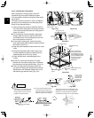
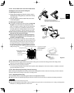
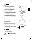
3-13-1. Before Installing the Ceiling Panel
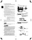
(1) Remove the air-intake grille and air filter from the
ceiling panel.
a) Slide the air-intake grille catches in the direction
shown by the arrows
1
to open the grille. (Fig. 3-40)
b) With the air-intake grille opened, remove the grille
hinge from the ceiling panel by sliding it in the
direction shown by the arrow
2
. (Fig. 3-41)
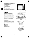
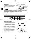
(2) Removing the corner cover
a) Remove the screws on the corner and slide the
latches in the direction of the arrow
1
to discon-
nect the hinges (3 locations). (Fig. 3-42) Then,
remove the air-intake grille in the direction of the
arrow
2
. (Fig. 3-43)
Screw
Latch
2
1
1
Air-intake grille
Ceiling panel
Air-intake grille hinge
Corner cover
2
1
1
Push
Corner cover
Ceiling panel
Fig. 3-37
Fig. 3-38
Fig. 3-39
Fig. 3-40
Fig. 3-41
Fig. 3-42 Fig. 3-43