


15
WARNING
Always check the gas density
limit for the room in which the
unit is installed.
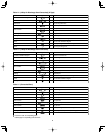
1-11. Check of Limit Density
When installing an air conditioner in a room, it is necessary
to ensure that even if the refrigerant gas accidentally leaks
out, its density does not exceed the limit level for that room.
If the density could exceed the limit level, it is necessary to
provide an opening between the unit and the adjacent room,
or to install mechanical ventilation which is interlocked with
a leak detector.
(Total refrigerant charged amount: oz)
(Min. indoor volume where the indoor unit is installed: ft.
3
)
<
Limit density 0.3 (oz/ft.
3
)
The limit density of refrigerant which is used in this unit is
0.3 oz/ft.
3
(ISO 5149).
The shipped outdoor unit comes charged with the amount of
refrigerant fixed for each type, so add it to the amount that
is charged in the field. (For the refrigerant charge amount at
shipment, refer to the unit’s nameplate.)
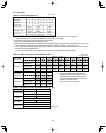
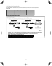
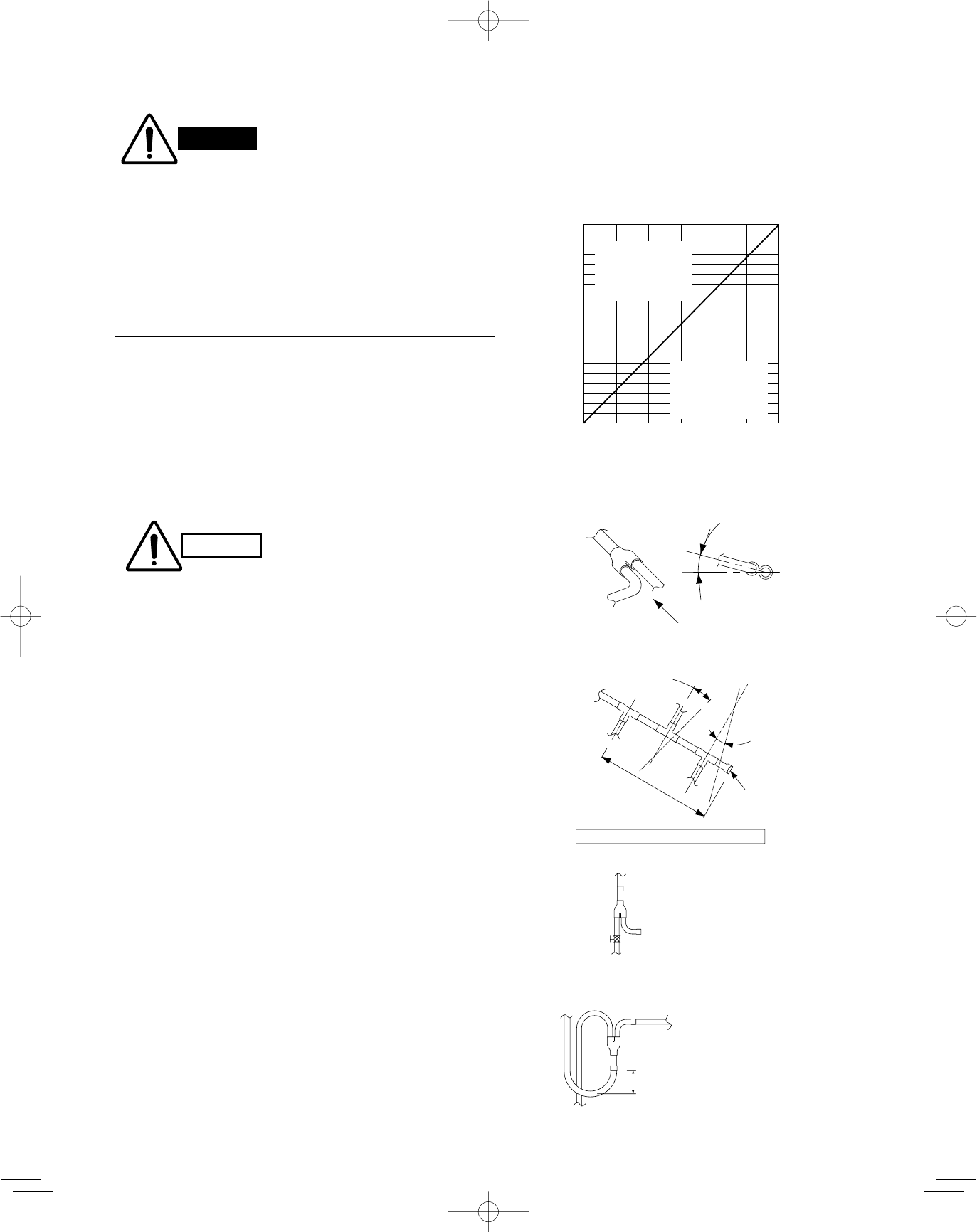
1-12. Installing Distribution Joint
Minimum indoor volume & floor area as against the
amount of refrigerant is roughly as given in the follow-
ing table.
00
57
114
170
227
284
341
398
454
511
568
625
682
738
795
852
909
966
1022
1079
1136
0
500
1000
1500
2000
2500
3000
3500
4000
4500
5000
5500
6000
6500
7000
7500
8000
8500
9000
9500
10000
1000500 1500 2000 2500 3000
Total amount of refrigerant
Min. indoor volume
Min. indoor floor area
(when the ceiling is 8.8 ft. high)
ft.
3
ft.
2
oz
Range above
the density limit of
0.3 oz/ft.
3
(countermeasures
needed)
Range below
the density limit of
0.3 oz/ft.
3
(countermeasures
not needed)
15 to 30
B
A
B
A
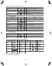
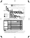
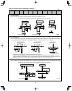
Tube branching methods (horizontal use)
Arrow view
Horizontal
line
View as seen
from arrow
Ball valve
(BV: purchased
separately)
Main tubing
Types of vertical trap specifications
(If only 1 unit is connected, a ball valve
is also needed on this side.)
Indoor unit (1)
(When not using ball valve)
(When using ball valve)
Branch tubing is
directed upward.
(Each unit is connected
to tubing that is either
level or is directed
downward.)
Main tubing
Indoor unit
More than
7–7/8"
Indoor unit (more than 2 units)
Horizontal
Indoor unit is directed downward
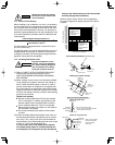
CAUTION
Pay special attention to any
location, such as a basement,
etc., where leaking refrigerant
can accumulate, since refrig-
erant gas is heavier than air.
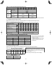
Outdoor
Indoor
Indoor
Indoor
Solidly welded
shut (X)
Horizontal
line
Horizontal
line
L3 6.56 ft.
Install at a
positive angle
Install at a
positive angle
(15 – 30°)
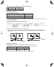
Header joint system (Indoor)
(1) Refer to “HOW TO ATTACH DISTRIBUTION JOINT”
enclosed with the optional distribution joint kit
(APR-CHRZP900BAB, RZP224BAB, RZP680BAB,
RZP1350BAB).
(2) When creating a branch using a commercially available
T-joint (header joint system), orient the main tubing so
that it is either horizontal (level) or vertical. In order to
prevent accumulation of refrigerant oil in stopped units,
if the main tubing is horizontal then each branch tubing
length should be at an angle that is greater than horizon-
tal. If the main tubing is vertical, provide a raised starting
portion for each branch.
[Header joint system]
●
Be sure to solidly weld shut the T-joint end (marked
by “X” in the figure). In addition, pay attention to the
insertion depth of each connected tube so that the
flow of refrigerant within the T-joint is not impeded.
●
When using the header joint system, do not make fur-
ther branches in the tubing.
●
Do not use the header joint system on the outdoor
unit side.
(3) If there are height differences between indoor units or if
branch tubing that follows a distribution joint is connect-
ed to only 1 unit, a trap or ball valve must be added to
that distribution joint. (When adding the ball valve, locate
it within 15 - 3/4" of the distribution joint.)
If a trap or ball valve is not added, do not operate
the system before repairs to a malfunctioning unit
are completed. (The refrigerant oil sent through the
tubing to the malfunctioning unit will accumulate
and may damage the compressor.)