


78
Unit side
insulator
Insulation tape (white)
(supplied)
Sealer (supplied)
Flare insulator (supplied)
Tube insulator
(not supplied)
Heat resistant
248°F or above
Vinyl clamps (supplied)
Flare nut
Fig. 6-8
Fig. 6-7
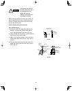
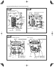
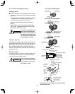
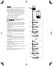
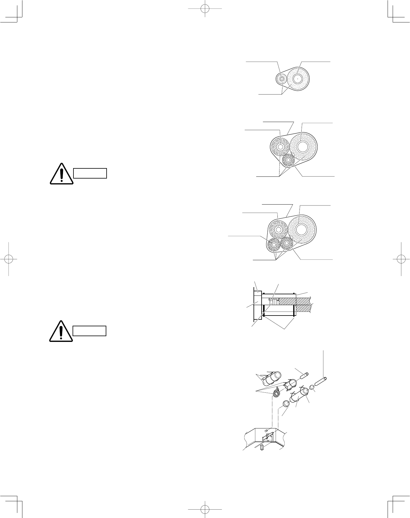
6-3. Insulating the Refrigerant Tubing
Tubing Insulation
●
Thermal insulation must be applied to all unit tubing,
including the distribution joint (purchased separately).
(Fig. 6-7)
* For gas tubing, the insulation material must be heat
resistant to 248°F or above. For other tubing, it
must be heat resistant to 176°F or above.
Insulation material thickness must be 25/64 in. or
greater.
If the conditions inside the ceiling exceed DB 86°F
and RH 70%, increase the thickness of the gas tub-
ing insulation material by 1 step.
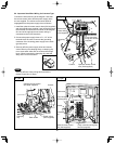
Taping the flare nuts
Wind the white insulation tape around the flare nuts at
the gas tube connections. Then cover up the tubing con-
nections with the flare insulator, and fill the gap at the
union with the supplied black insulation tape. Finally,
fasten the insulator at both ends with the supplied vinyl
clamps. (Fig. 6-8)
Insulation material
The material used for insulation must have good insula-
tion characteristics, be easy to use, be age resistant,
and must not easily absorb moisture.
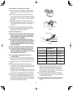
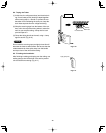
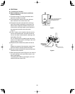
After a tube has been insulated,
never try to bend it into a narrow
curve because it can cause the
tube to break or crack.
CAUTION
CAUTION
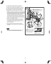
Never grasp the drain or refrigerant connecting outlets
when moving the unit.
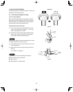
The procedure used for
installing the insulator for
both gas and liquid
tubes are the same.
Seal
Flare
insulator
Vinyl
clamp
Insulation
tape
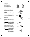
Refrigerant tubing and insulator
(not supplied)
Drain pipe and insulator
(not supplied)
Drain insulator
and clamp.
Large
(supplied)
Packing
clamp.
Small
hose band
(supplied)
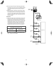
Gas tubing
Liquid tubing
Insulation
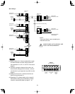
Three tubes arranged together
Two tubes arranged together
If the exterior of the outdoor unit
valves has been finished with a
square duct covering, make sure
you allow sufficient space to use
the valves and to allow the panels
to be attached and removed.
Fig. 6-9
Cosmetic
(finishing) tape
Liquid tubing
Gas tubing
Insulation
Balance tubing
Suction tubing
Cosmetic
(finishing) tape
Discharge tubing
Liquid tubing
Balance tubing
Insulation
Four tubes arranged together