


60
K
■
Wall-Mounted Type (K Type)
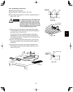
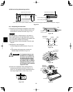
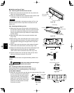
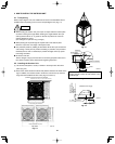
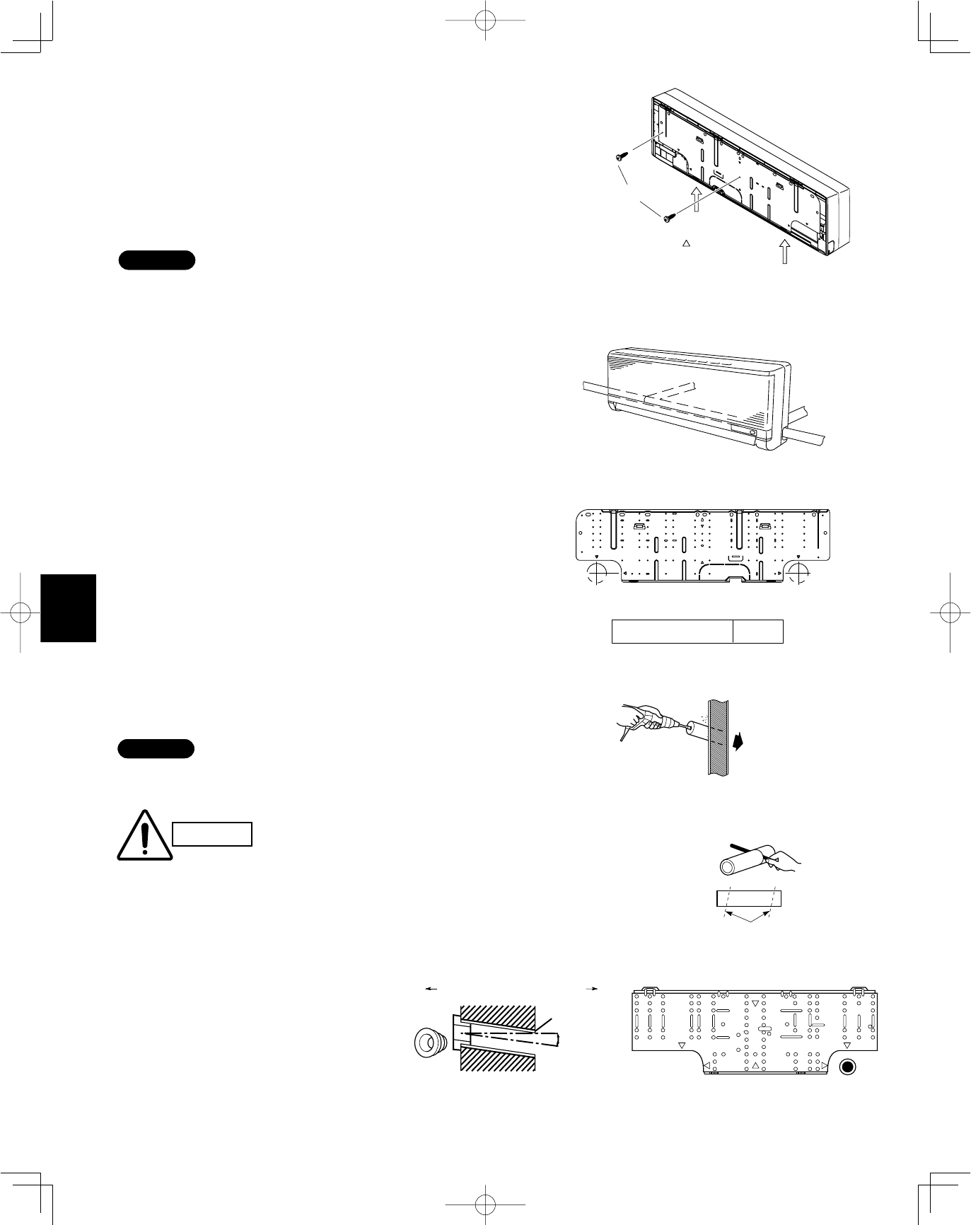
3-35. Removing the Rear Panel from the Unit
(1) Remove the set screws used to fasten the rear panel to the
indoor unit during transportation.
(2) Press up on the frame at the 2 locations shown by the arrows
in the figure at right, and remove the rear panel.
NOTE
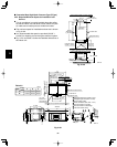
Tubing can be extended in 4 directions as shown in Fig. 3-134.
Select the direction which will provide the shortest run to the
outdoor unit.
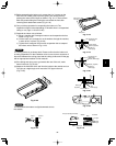
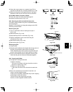
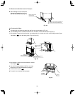
3-36. Selecting and Making a Hole
(1) Remove the rear panel from the indoor unit and place it on
the wall at the location selected. Fix the rear panel and hook
the unit onto it temporarily. Make sure the unit is horizontal
using a carpenter’s level or tape measure to measure down
from the ceiling.
(2) Determine which notch of the rear panel should be used.
(Fig. 3-135)
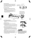
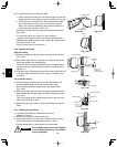
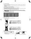
(3) Before drilling a hole, check that there are no studs or pipes
behind the determined location. The above precautions are
also applicable if tubing goes through the wall in any other
location.
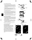
(4) Using a sabre saw, key hole saw or hole-cutting drill attach-
ment, make a hole (dia. 3-5/32") in the wall. (Fig. 3-136)
(5) Measure the thickness of the wall from the inside edge to the
outside edge and cut the PVC pipe at a slight angle
15/64" shorter than the thickness of the wall. (Fig. 3-137)
(6) Place the plastic cover over the end of the pipe (for indoor
side only) and insert in the wall. (Fig. 3-138)
NOTE
The hole should be made at a slight downward gradient to the
outside.
Fig. 3-133
Fig. 3-134
Fig. 3-135
Fig. 3-136
Fig. 3-137
CAUTION
Avoid areas where electrical wiring or
conduits are located.
Cut at slight angle
PVC pipe (locally purchased)
Indoor
side
Outdoor
side
Tubing hole diameter ø3-5/32
Center of left rear
tubing hole
Center of right rear
tubing hole
Left tubing
Right-rear
tubing
(recommended)
Right tubing
Left-rear tubing
Press
Remove the rear panel
Screws used during
transportation
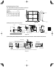
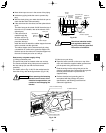
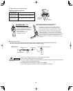
3-37. Installing the Rear Panel onto the Wall
Confirm that the wall is strong enough to support the unit.
See either Item a) or b) below depending on the wall type.
a) If the Wall is Wooden
(1) Attach the rear panel to the wall with the 10 screws provided. (Fig. 3-139)
If you are not able to line up the holes in
the rear panel with the beam locations
marked on the wall, use Rawl plugs or
toggle bolts to go through the holes on
the panel or drill 3/16" dia. holes in the
panel over the stud locations and then
mount the rear panel.
Fig. 3-139
Fig. 3-138
Plastic
cover
INSIDE
Wall
Slight
angle
PVC pipe
OUTSIDE