


14
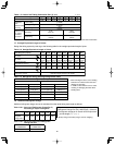
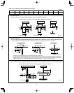
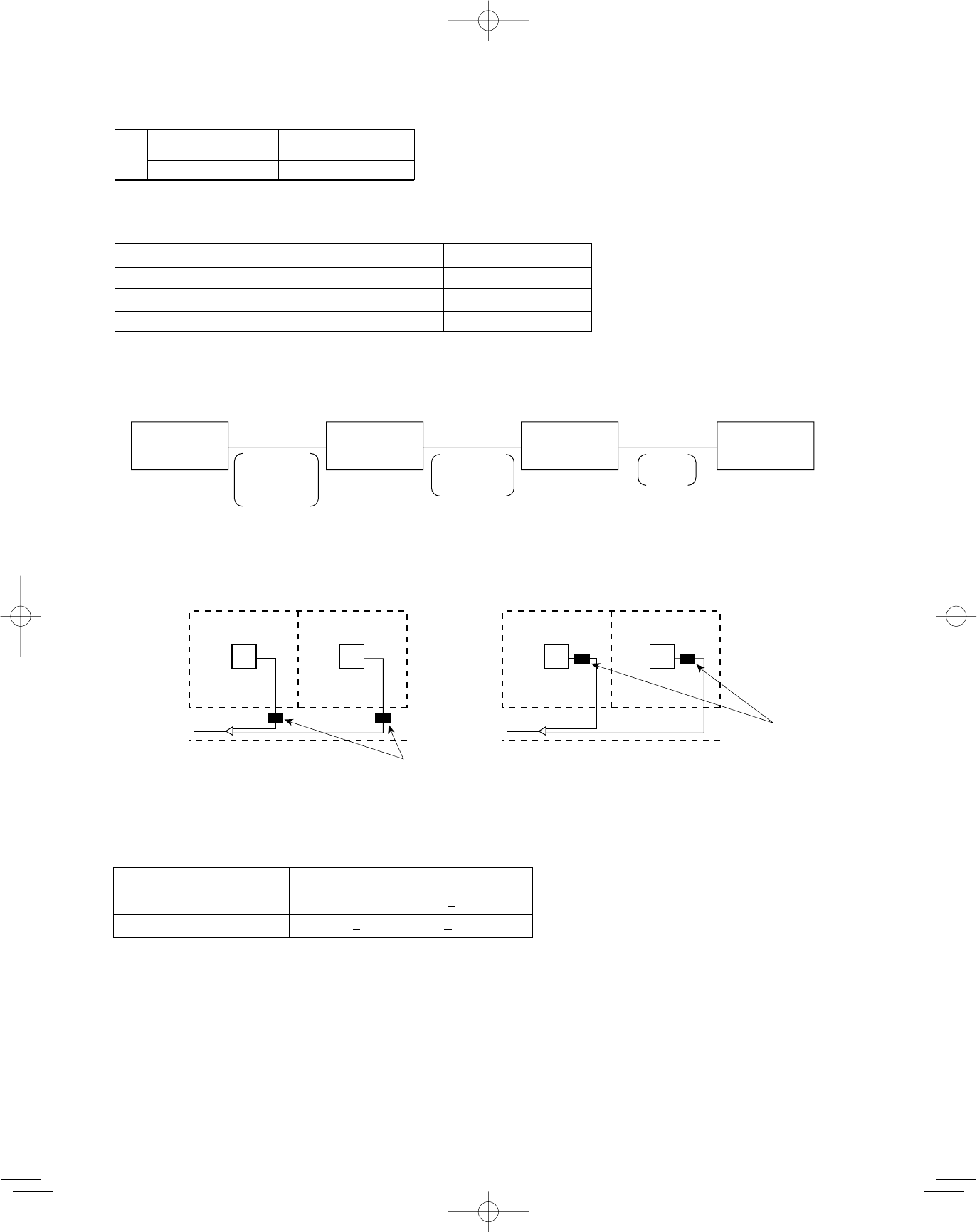
Common solenoid valve kit
●
Multiple indoor units under group control can utilize a solenoid valve kit in common.
●
Categories of connected indoor unit capacities are determined by the solenoid valve kit.
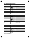
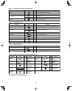
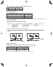
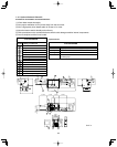
Table 1-17 Refrigerant Charge Amount at Shipment (for outdoor unit)
DC
CHDZ09053 CHDZ14053
CHDZR09053 CHDZR14053
(oz)
416 416
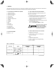
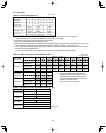
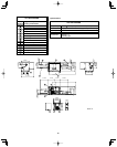
1-9. System Limitations
Table 1-18 System Limitations
Max. No. allowable connected outdoor units 2
Max. capacity allowable connected outdoor units
307,100 BTU/h (32 hp, 90 kw)
Max. connectable indoor units 40
*1
Max. allowable indoor/outdoor capacity ratio 50 – 130 %
Type of solenoid valve kit Total capacity of indoor units (BTU/h)
160 19.000
<
Total capacity
<
54.600
56 7.500
<
Total capacity
<
19.000
*1: In the case of 20 hp (type 191.100 BTU/h) or smaller units, the number is limited by the total capacity of the connected indoor units.
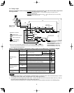
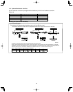
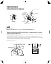
1-10. Installation Standards
Relationship between A/C units and refrigerant tubing
Outdoor unit Outdoor unit Indoor unit
Suction tube
Discharge tube
Liquid tube
Balance tube
Suction tube
Discharge tube
Liquid tube
Gas tube
Liquid
tube
4-tube layout 3-tube layout 2-tube layout
Solenoid
valve kit
Indoor unit
Room
Hallway
Indoor unit
Room
Indoor unit
Room
Hallway
Indoor unit
Room
Solenoid
valve kit
Solenoid
valve kit
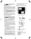
●
Install the solenoid valve kit 98 ft. or less from the indoor unit.
●
In quiet locations such as hospitals, libraries, and hotel rooms, the refrigerant noise may be somewhat notice-
able. It is recommended that the solenoid valve kit be installed inside the corridor ceiling, at a location outside
the room.
YES
NO
●
If the capacity range is exceeded, use 2 solenoid valves connected in parallel.