


38
XM
●
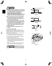
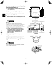
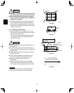
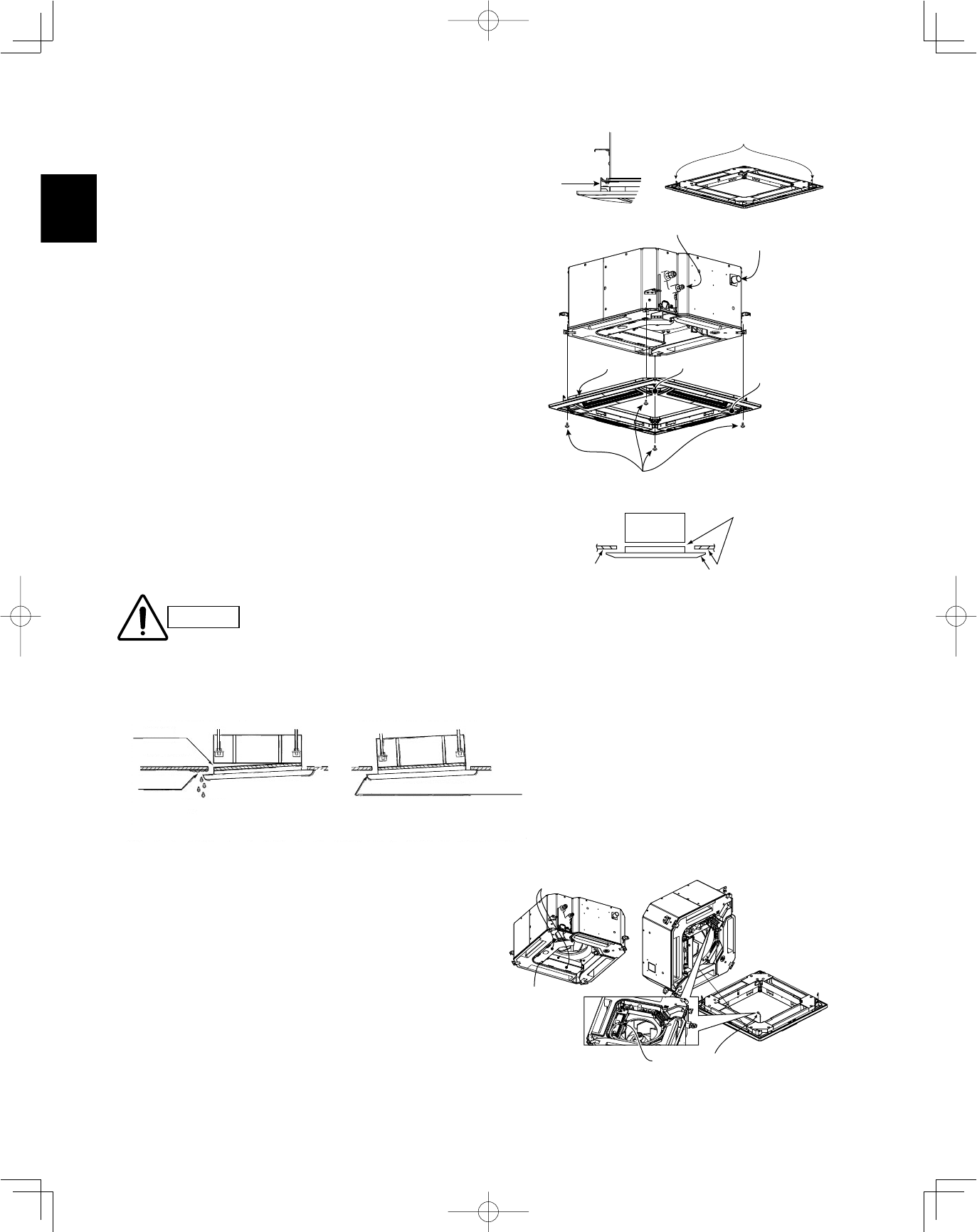
If the screws are not sufficiently tight-
ened, trouble such as that shown in
the figure below may occur. Be sure to
tighten the screws securely.
●
If a gap remains between the ceil-
ing surface and the ceiling panel
even after the screws are tightened,
adjust the height of the unit again.
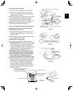
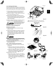
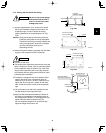
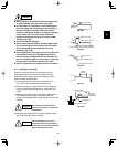
3-13-3. Wiring the Ceiling Panel
(1) Open the cover of the electrical component box for
control PCB.
(2) Connect the 7P wiring connector (red) from the ceil-
ing panel to the connector on the control PCB in the
unit electrical component box. (Fig. 3-48)
●
If the connectors are not connected, the Auto flap will not
operate. Be sure to connect them securely.
●
Check that the wiring connector is not caught between the
electrical component box and the cover.
●
Check that the wiring connector is not caught between the
unit and the ceiling panel.
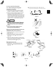
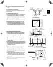
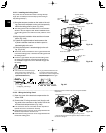
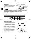
3-13-2. Installing the Ceiling Panel
The power must be turned ON in order to change the flap
angle. (Do not attempt to move the flap by hand. Doing so
may damage the flap.)
(1) Hang the temporary latches on the inside of the ceil-
ing panel to the receptacle on the unit to temporarily
attach the ceiling panel in place. (Fig. 3-44)
●
The ceiling panel must be installed in the correct direction
relative to the unit. Align the REF. PIPE and DRAIN marks
on the ceiling panel corner with the correct positions on the
unit.
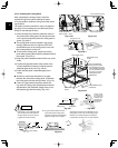
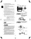
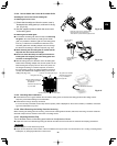
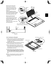
(2) Align the panel installation holes and the unit screw
holes. (Fig. 3-45)
(3) Tighten the supplied washer head screws at the
4 panel installation locations so that the panel is
attached tightly to the unit.
(4) Check that the panel is attached tightly to the ceil-
ing. (Fig. 3-46)
●
At this time, make sure that there are no gaps between the
unit and the ceiling panel, or between the ceiling panel and
the ceiling surface.
●
If there is a gap between the panel and the ceiling, leave
the ceiling panel attached and make fine adjustments to
the installation height of the unit to eliminate the gap with
the ceiling.
(Direction that the unit faces has been changed to facilitate
explanation.)
* Pass the wiring connector through the clamp to fasten it in place,
as shown in the figure.
CAUTION
Temporary
latch
Temporary latches
Refrigerant tubing joint
Drainage check
DRAIN mark
REF. mark
Ceiling panel
Washer head screws
Panel installation hole
(4 locations)
Main unit
Ceiling panel
Ceiling surface
Do not allow
gaps
Adjust so that there are no gaps.
Condensation, water leakage
Staining
Air leakage from
ceiling surface
Air leakage
Electrical component box cover
Ceiling panel wiring connector
Screws
(3 locations)
Fig. 3-44
Fig. 3-45
Fig. 3-46
Fig. 3-48
Fig. 3-47