


21
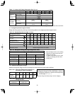
1-15. Example of Tubing Size Selection and Refrigerant Charge Amount
Additional refrigerant charging
Based on the values in Tables 1-10, 11, 12, 15 and 16-2 use the liquid tubing size and length, and calculate the amount of additional
refrigerant charge using the formula below.
Required additional
refrigerant charge (oz)
=
Necessary Amount of Refrigerant Charge Per Unit + 3.93
×
(a) + 2.78
×
(b) + 1.99
×
(c) + 1.38
×
(d) +
0.602
×
(e) + 0.279
×
(f)
(a) : Liquid tubing Total length of ø7/8" (ft.) (d) : Liquid tubing Total length of ø1/2" (ft.)
(b) : Liquid tubing Total length of ø3/4" (ft.) (e) : Liquid tubing Total length of ø3/8" (ft.)
(c) : Liquid tubing Total length of ø5/8" (ft.) (f ) : Liquid tubing Total length of ø1/4" (ft.)
●
Charging procedure
Be sure to charge with R410A refrigerant in liquid form.
1. After performing a vacuum, charge with refrigerant from the liquid tubing side. At this time, all valves must be in the “fully
closed” position.
2. If it was not possible to charge the designated amount, operate the system in Cooling mode while charging with refrigerant
from the gas tubing side. (This is performed at the time of the test run. For this, all valves must be in the “fully open” position.
However if only one outdoor unit is installed, a balance tube is not used. Therefore, leave the valves fully closed.)
Charge with R410A refrigerant in liquid form.
With R410A refrigerant, charge while adjusting the amount being fed a little at a time in order to prevent liquid refrigerant from
backing up.
●
After charging is completed, turn all valves to the “fully open” position.
●
Replace the tubing covers as they were before.
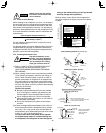
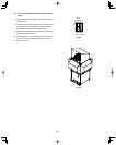
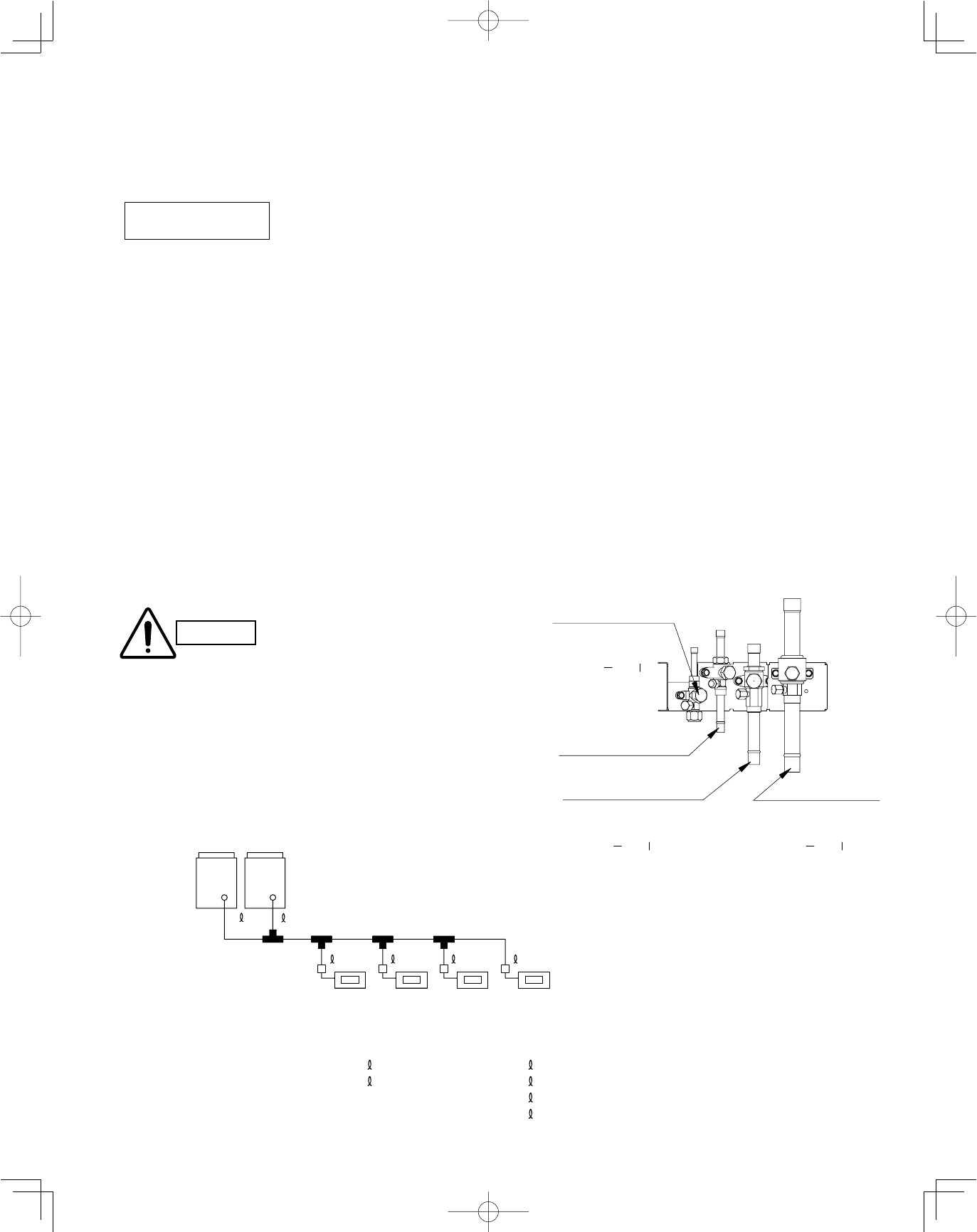
CAUTION
1. R410A additional charging absolutely must
be done through liquid charging.
2. The R410A refrigerant cylinder has a gray
base color, and the top part is pink.
3. The R410A refrigerant cylinder includes a
siphon tube. Check that the siphon tube is
present. (This is indicated on the label at
the top of the cylinder.)
4. Due to differences in the refrigerant, pres-
sure, and refrigerant oil involved in instal-
lation, it is not possible in some cases to
use the same tools for R22 and for R410A.
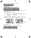
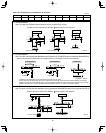
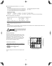
1 2 3 4
LA
LB
LC
A
B
Outdoor unit
09053
model
09053
model
48 model 48 model 48 model 36 model
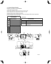
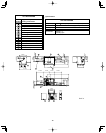
Example:
●
Example of each tubing length
Main tubing Distribution joint tubing
LA = 131 ft. Outdoor side Indoor side
LB = 16 ft.
A = 7 ft. 1 = 98 ft.
LC = 16 ft.
B = 7 ft. 2 = 16 ft.
3 = 16 ft.
4 = 65 ft.
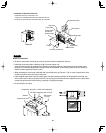
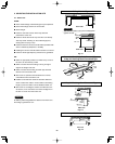
Balance tube
Liquid tube
Discharge tube
Suction tube
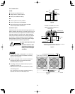
Use a hex wrench (width 5/32 inch)
and turn to the left to open.
Use a flathead screwdriver
and open by turning the part
with the screw groove to the
right, from " " to " "
Use a flathead screwdriver
and open by turning the part
with the screw groove to the
right, from " " to " "
Use a flathead screwdriver
and open by turning the part
with the screw groove to the
right, from " " to " "