


82
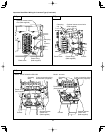
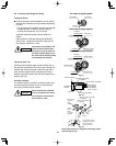
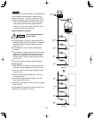
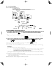
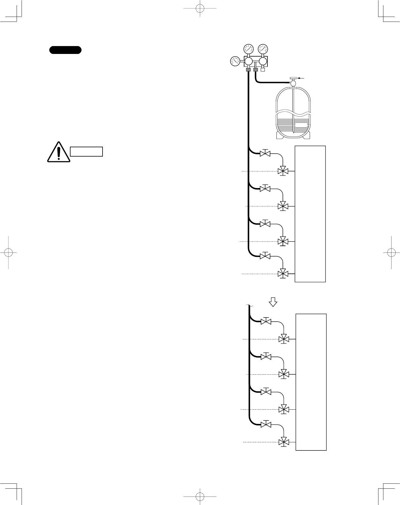
Fig. 7-5
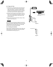
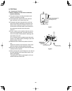
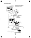
Fig. 7-6
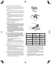
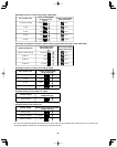
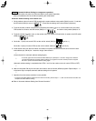
NOTE
The required time in the above table is calculated based
on the assumption that the ideal (or target) vacuum
condition is less than –14.7 psig (–755 mm Hg, 5 Torr).
(2) When the desired vacuum is reached, close the “Lo”
knob of the manifold valve and turn off the vacuum
pump. Please confirm that the gauge pressure is
under –14.7 psig (–755 mm Hg, 5 Torr) after 4 to 5
minutes of vacuum pump operation.
Charging additional refrigerant
●
Charging additional refrigerant (calculated from the
liquid tube length as shown in Section 1-8 “Additional
Refrigerant Charge”) using the liquid tube service
valve. (Fig. 7-5)
●
Use a balance or scale to measure the refrigerant
accurately.
●
If the additional refrigerant charge amount cannot be
charged at once, charge the remaining refrigerant in
liquid form by using the suction tube service valve
with the system in Cooling mode at the time of test
run. (Fig. 7-6)
●
Close the valve on the cylinder containing R410A.
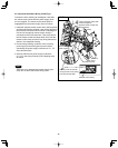
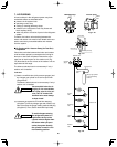
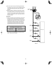
Finishing the job
(1) With a flathead screwdriver, turn the liquid tube ser-
vice valve counter-clockwise to fully open the valve.
(2) Turn the all service valve counter-clockwise to fully
open the valve.
(3) Close all stop valves and loosen the “LO” knob of
the manifold valve.
(4) Loosen the charge hose connected to all service
port, then remove the hose.
(5) Replace all valve caps at all service ports and fasten
them securely.
This completes air purging with a vacuum pump. The air
conditioner is now ready for a test run.
CAUTION
Use a cylinder designed for
use with R410A.
Valve
Liquid
Manifold valve
Pressure
gauge
Lo Hi
Outdoor unit
Close
Open
Discharge
tube
Suction
tube
Liquid
tube
Close
Close
Balance
tube
Close
Close
Close
Close
R410A
Outdoor unit
Open
Close
Discharge
tube
Suction
tube
Liquid
tube
Open
Close
Balance
tube
Open
Close
Open
Open