29733 R2 06/01/2003
9
installed in accordance to the instructions supplied with
the regulator.
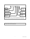
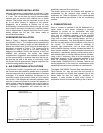
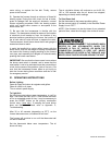
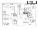
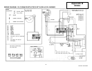
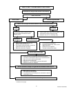
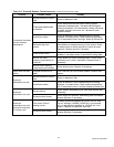
8. FURNACE CONTROLS
The furnace is controlled by either of two systems,
depending on the oil primary control and electronic fan
timer combination. System 1, used with Beckett burners,
includes the blower mounted Honeywell ST9103
E
LECTRONIC FAN TIMER (EFT) combined with the R7184
O
IL PRIMARY CONTROL. System 2, used with Riello
burners, includes the blower mounted Honeywell ST9103
E
LECTRONIC FAN TIMER (EFT) combined with a
transformer / burner relay mounted internally on the 40F3
burner housing to operate the oil burner.
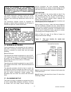
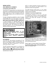
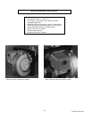
Figure 3: R7184 Oil Primary
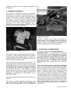
The furnace functions are controlled by either System 1
or System 2, and bi-metallic snap disc limit switches.
These groupings also provide control for add-on air
conditioning. The ST9103 EFT is located in a control box
mounted to the blower support rails.
The circulating fan is controlled by the ST9103 EFT. The
heat delay-on time is fixed, at 30 seconds. This provides
a delay between the start of the burner and the start of
the circulating fan to reduce the amount of ambient
unheated air flowing through the ductwork. The end of
the circulating fan cycle is also delayed to remove
residual heat from the furnace. There are four delay-off
choices, 60, 90, 120 and 150 seconds, which are field
adjustable by manipulating the DIP switches on the
ST9103 EFT board.
The cooling delay-on and delay-off times are fixed at 30
seconds.
The furnace is protected against over-heating by fixed
high temperature limits. These controls are factory set
and are not field adjustable. If an over temperature
condition is detected, one or both limit switches will
interrupt power to the oil primary control, which will shut
of the oil burner. The circulating fan will continue to
operate. The high limit switches will automatically reset
when the furnace returns to a safe temperature.
9. ELECTRICAL CONNECTIONS
The furnace is listed by the Canadian Standards
Association (CSA). It is factory wired and requires
minimal field wiring. In the United States, the wiring must
be in accordance with the National Fire Protection
Association NFPA-70, National Electrical Code, and
with local codes and regulations. In Canada, all field
wiring should conform to CAN/CSA C22.1 Canadian
Electrical Code, Part 1, and by local codes, where they
prevail.
The furnace should be wired to a separate and dedicated
circuit in the main electrical panel; however, accessory
equipment such as electronic air cleaners and humidifiers
may be included on the furnace circuit. Although a
suitably located circuit breaker can be used as a service
switch, a separate service switch is advisable. The
service switch is necessary if reaching the circuit breaker
involves becoming close to the furnace, or if the furnace
is located between the circuit breaker and the means of
entry to the furnace room. The furnace switch (service
switch) should be clearly marked, installed in an easily
accessible area between the furnace and furnace room
entry, and be located in such a manner to reduce the
likelihood that it would be mistaken as a light switch or
similar device.
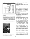
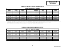
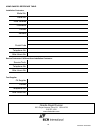
Figure 4: ST9103 EFT