29733 R2 06/01/2003
31
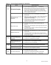
R7184 LED DIAGNOSTIC LIGHT
The LED diagnostic light has several functions. It
indicates the state or mode in which the oil burner is
operating. It will also indicate fault conditions, and help
determine cad cell resistance while the burner is
operating.
N
ORMAL CONDITIONS:
The LED diagnostic light will turn on when the burner
enters the carryover state; the point at which ignition
spark is on, and will remain on through the run state,
where the ignition spark is terminated but the burner
continues to fire.
The LED diagnostic light will turn off at the end of the
burner cycle as the R7184 enters the idle state, and
will remain off until the next heating cycle.
F
AULT CONDITIONS:
If the LED diagnostic light is flashing quickly; 1 Hz (½
second on / ½ second off), the R7184 is in the lockout
state or in restricted mode. To exit the lockout state,
press the reset button.
If the LED diagnostic light is flashing slowly; ¼ Hz (2
seconds on / 2 seconds off), the R7184 is in the
recycle state. This indicates that flame sensing was
lost after the lockout timer expired during the ignition
carryover state. The R7184 will return to the idle state
within 60 seconds.
C
AD CELL CONDITION:
If the LED diagnostic light is off, the cad cell is not
sensing flame.
If the LED diagnostic light is on, the cad cell is sensing
flame, or viewing ambient light.
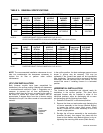
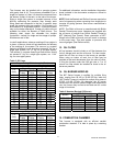
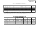
The resistance of the cad cell may be checked while
the R7184 is in the run state
by pressing the reset
button. The LED diagnostic light will flash the following
code:
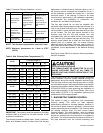
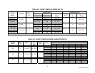
TABLE C-2: CAD CELL RESISTANCE
Flashes Resistance in Ohms
1 Less than 400
2 Between 400 - 800
3 Between 800 – 1600
4 Between 1600 - 5000
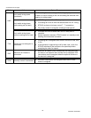
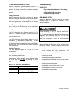
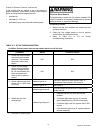
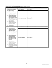
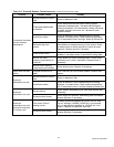
Troubleshooting
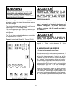
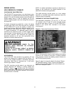
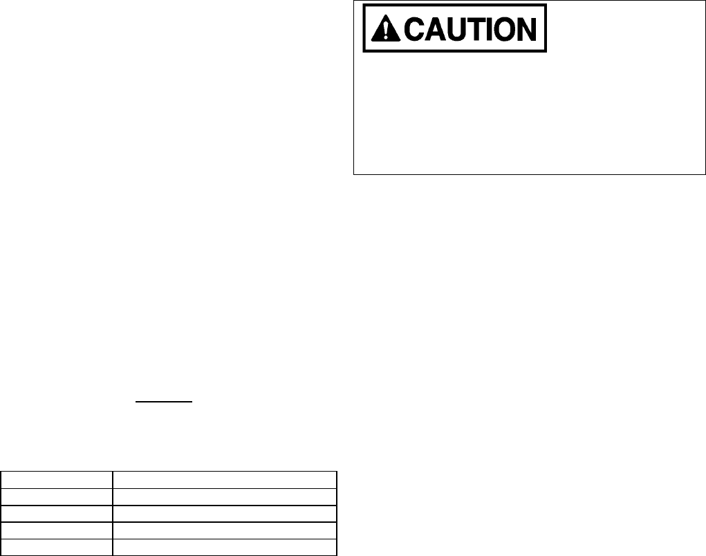
IMPORTANT:
Due to the potential hazard of line voltage,
only a trained, experienced service
technician should perform the
troubleshooting procedure.
PRELIMINARY STEPS:
Check the diagnostic light for indications of burner
condition. Refer to R7184 LED
DIAGNOSTIC LIGHT
section for details.
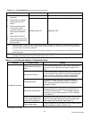
When simulating a call for heat at the R7184,
disconnect at least one thermostat lead wire from the
T1 - T2 terminals to prevent damage to the thermostat.
Neglecting this procedure may burn out the heat
anticipator of a standard 24 VAC thermostat, or cause
harm to components within a micro-electronic
thermostat.
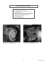
Before checking the oil primary control, perform these
preliminary checks, (repair or replace controls as
necessary):
· check the power supply; fuse box or breaker, any
service switches, all wiring connections, and
burner motor reset button (if equipped).
· check the limit switches to ensure that the switch
contacts are closed.
· check the electrode gap and position.
· check the contacts between the oil primary control
and the electrodes.
· check oil supply (tank gauge).
· check the oil nozzle, oil filter, and oil valves.
· check the piping or tubing to the oil tank.
· check the oil pump pressure.