


29733 R2 06/01/2003
12
CHECK THE ALIGNMENT OF THE COMBUSTION
CHAMBER AND OIL BURNER BEFORE FIRING. IT
IS POSSIBLE FOR THE COMBUSTION CHAMBER
TO SHIFT IF SUBJECTED TO ROUGH HANDLING
DURING TRANSIT.
The cerafelt combustion chamber is quite soft initially.
After firing, it becomes very brittle. Be sure to do all
alignment and positioning adjustments before the first
firing.
The combustion chamber should be inspected for
damage or carbon build up whenever the oil burner is
removed for repairs or routine maintenance.
BEFORE OPERATING THE FURNACE CHECK
BURNER ALIGNMENT WITH COMBUSTION
CHAMBER. THE END CONE OF THE AIR TUBE
MUST BE CENTRED TO THE ACCOMODATING
RING PROVIDED IN THE DESIGN OF THE
COMBUSTION CHAMBER. ADJUST ALIGNMENT
AND AMULET POSITION (RIELLO BURNER) AS
NECESSARY BEFORE FIRST FIRING.
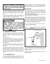
16. BURNER ELECTRODES
Correct positioning of the electrode tips with respect to
each other, to the fuel oil nozzle, and to the rest of the
burners is essential for smooth light ups and proper
operation.
Beckett Oil Burner:
The electrode tips should be adjusted to a gap of 5/32”,
1/16” ahead of the nozzle, 5/16” above the centerline of
the nozzle. The “Z” dimension (front edge of the burner
head to the front face of the nozzle is 1-1/8 inches.
Riello Oil Burner:
The electrode tips should be adjusted to a gap of 5/32”,
3/32” ahead of the nozzle, 13/64” above the centerline of
the nozzle.
The electrode porcelains should be free of cracks, the
electrode tips should be tapered and free of burrs, and
the contact rods must be clean and be in firm contact
with the ignition transformer contact springs. The
electrodes must not come into contact with the burner
head.
17. OIL BURNER SET UP
The burner air supply is adjusted to maintain the fuel to
air ratio to obtain ideal combustion conditions. A lack of
air causes "soft" and "sooty" flames, resulting in soot
build-up throughout the heat exchanger passages.
Excess combustion air causes a bright roaring fire and
high stack temperatures resulting in poor fuel efficiency.
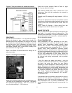
PREPARATIONS:
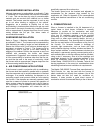
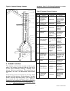
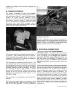
Drill a ¼” test port in the venting, ideally at least 2 flue
pipe diameters away from the furnace breeching, if
venting horizontally from the furnace, or from the flue
pipe elbow if venting vertically before reaching the
furnace. (see Figures 5 and 6).
The test port will allow flue gas samples to be taken and
stack temperatures to be measured.
Before starting the burner, check the burner alignment
with the combustion chamber (fire pot), check that the
correct nozzle is tightened into place, and that the burner
electrodes are properly positioned. The Beckett burner
bulk air band is should be closed, and the air shutter
initial setting should be approximately 7.00.
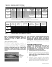
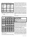
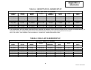
Refer to Table A-2, page 18, for Riello oil burner air
damper and turbulator settings.
Figure 5: Test port location for smoke test
horizontal.
Note A: Locate hole at least 6 inches on the furnace side
of the draft control.
Note B: Ideally, hole should be at least 12 inches from
breeching or elbow.