


29733 R2 06/01/2003
24
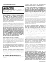
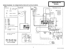
WIRING NOTES:
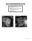
HO-B SERIES OIL FURNACE
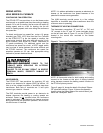
CONTINUOUS FAN OPERATION:
The ST9103 EFT has provisions to run the blower motor
continuously on a speed lower than the cooling or heating
speeds. On a call for cooling, the fan motor will switch to
cooling speed, and on a call for heating, the fan will
switch to heating speed, each over-riding the continuous
low speed fan.
To obtain continuous low speed fan, route a 16 gauge
stranded, type TEW, 105°C wire from the C
ONT Terminal
on the ST9103 EFT to the low speed or medium low
speed motor terminal. Both wire ends will require ¼ inch
quick connects, (also known as “Faston” connectors or
¼” spade connectors). For additional control over the
continuous low speed fan circuit, a SPST toggle switch
may be wired in series between the motor terminal and
the ST9103 terminal. The continuous low speed fan
operation operates at 115 vac. Use appropriate wiring
methods to prevent electrical shock.
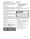
TURN OFF ELECTRICAL POWER TO THE
FURNACE WHEN SERVICING OR ALTERING
FURNACE WIRING.
FAILURE TO DO SO MAY RESULT IN SEVERE
PERSONAL INJURY, PROPERTY DAMAGE OR
DEATH.
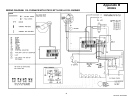
ACCESSORIES:
The ST9103 EFT has provisions for supplying 115 volt
power to an electronic air cleaner (EAC) as well as 115
volts to a line voltage humidifier or humidifier step down
transformer. Both sets of terminals are ¼ inch quick
connect type, rated at 1 A each.
The EAC terminals provide power to an electronic air
cleaner whenever the heating or cooling speeds are
activated. Power is not
provided when the continuous
speed is activated. If the electronic air cleaner must run
during continuous low speed fan operation, wire the EAC
into the furnace L1 terminal.
NOTE: It is seldom advisable to operate an electronic air
cleaner at the continuous low speed because of the
potential for excess ozone generation.
The HUM terminals provide power to a line voltage
humidifier or humidifier step down transformer when the
oil burner motor is operating.
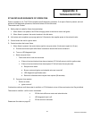
THERMOSTAT HEATING CONNECTIONS:
The thermostat connections “R” and “W”, or “R
H” and
“W” connect to the “R” and “W” screw terminals shown
on the left hand side of Figure 10, on the ST9103 EFT
located in the control box mounted to the blower
mounting rails.
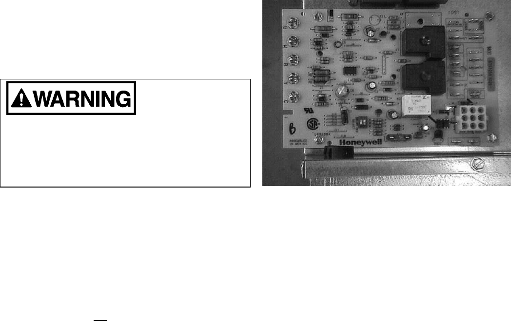
Figure 9: Thermostat Connections ST9103
NOTE: All thermostat wires for both heating and cooling
connect to the furnace at this point. A factory installed
wiring harness connects the heating control functions to
the R7184 oil primary control.
Figure 8, page 14, shows the detail of the timed “Blower
Off” dipswitch settings. Figure 10 shows the dipswitch
location along the bottom edge of the control board, just
above the “Honeywell” label.