


29733 R2 06/01/2003
11
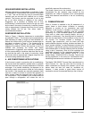
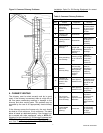
The furnaces may be installed with a one-pipe system
with gravity feed or lift. The maximum allowable lift on a
single line system is 8 feet. Lift should be measured from
the bottom (outlet) of the tank, to the inlet of the burner.
Sizing a single line system is complex because of the
difficulty estimating the pressure drop through each
fitting, bend and component in the line. In general, keep
single line systems short as possible. If the furnace is to
be installed in a suspended position, a two-pipe system
may be the better alternative. 2-stage oil pumps are not
available for either the Beckett or Riello burner. The
following chart shows the allowable line lengths
(horizontal + vertical) for single and two stage oil pumps.
All distances are in feet.
In retrofit applications, where an existing oil line system is
in place, a vacuum check will help determine the efficacy
of the existing oil line system The vacuum in a system
featuring a Beckett burner should not exceed 6” Hg. for a
single pipe system, nor 12” Hg. for a two-pipe system.
The vacuum in a system featuring a Riello burner should
not exceed 6” Hg. for a single pipe system, nor 11.44”
Hg. for a two-pipe system.
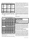
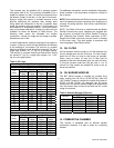
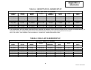
Table 5: Oil Lines
Copper Tubing Oil Line Lengths (Feet)
Beckett Oil Burner
Single-Pipe Two-Pipe
Lift
(feet)
⅜” O.D.
Tubing
½” O.D.
Tubing
⅜” O.D.
Tubing
½” O.D.
Tubing
0 53 100 68 100
1 49 100 65 100
2 45 100 63 100
3 41 100 60 100
4 37 100 58 100
5 33 100 55 100
6 29 100 53 100
7 25 99 50 100
8 21 83 48 100
9 17 68 45 100
10 13 52 42 100
12 - - - - - - 37 100
14 - - - - - - 32 100
16 - - - - - - 27 100
18 - - - - - - 22 88
Riello Oil Burners
Single-Pipe Two-Pipe
Lift
(feet)
⅜” O.D.
Tubing
½” O.D.
Tubing
⅜” O.D.
Tubing
½” O.D.
Tubing
1.5 33 65 100 330
3.0 65 130 80 330
5.0 130 260 65 295
6.5 195 325 50 230
9.5 - - - - - - 25 100
11 - - - - - - 20 65
For additional information, see the installation information
sheet included in the documents envelope or affixed to
the oil burner.
NOTE: Both the Beckett and Riello oil burners require the
use of a bypass plug when converting from single-pipe to
two-pipe oil piping systems. See burner manufacturer’s
instructions.
NOTE: The Riello oil burner is manufactured with British
Parallel Thread pump ports. Adapters are supplied with
the oil burner to convert from British Parallel Thread to
NPT (National Pipe Thread). Direct connection of NPT
fittings to the Riello oil burner ports will result in damage
to the pump body. This also applies to pressure and
vacuum gauges. (See Riello manual)
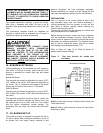
13. OIL FILTER
All fuel systems should include an oil filter between the
fuel oil storage tank and the oil burner. For best results,
install the oil filter as close to the burner as possible.
When using an indoor oil tank, the oil filter may be
installed at the tank downstream from the shut-off valve.
If firing the furnace under the 0.65 gph rate, a 7 to 10
micron line filter should be installed as close to the oil
burner as possible.
14. OIL BURNER NOZZLES
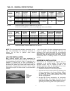
The 80F Series furnace is certified for multiple firing
rates, ranging from 58,100 to 78,900 BTU/hr, while the
120F Series Furnace is certified for multiple firing rates of
87,000 113,400 BTU/hr. By changing the oil burner
nozzle within the specific Model Range, and temperature
rise, the furnace may be fired at an ideal rate for a wide
range of structures.
Table 6: Nozzles (Beckett Oil Burner)
NOZZLE (Delavan) HEAD
MODEL
STD. ALT.
80F (060) 0.50/70°W 0.50/80°A F0
80F (070) 0.65/70°W 0.65/80°A F3
80F (080) 0.70/70°W 0.70/80°A F3
120F (090) 0.75/70°W 0.75/80°A F4
120F (100) 0.80/70°W 0.80/80°A F4
120F (120) 1.00/70°W 1.00/80°A F4
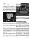
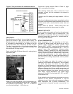
15. COMBUSTION CHAMBER
This furnace is equipped with an efficient cerafelt
combustion chamber. It is held in place by a retaining
bracket.