


29733 R2 06/01/2003
4
1. INTRODUCTION
Please read these instructions completely and carefully
before installing and operating the furnace.
The furnace must be installed and set up by a qualified
contractor
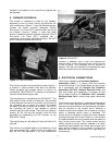
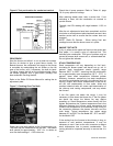
MODEL 80F
Model 80F is an oil-fired upflow forced air furnace, with
an output capacity range of 58,100 BTU/Hr. to 78,900
BTU/Hr. The 80F furnace equipped with a direct drive
blower may be installed in both horizontal positions.
MODEL 120F
Model 120F is an oil-fired upflow forced air furnace, with
an output capacity range of 87,700 BTU/Hr. to 113,400
BTU/Hr. The 120F furnace equipped with a direct drive
blower may be installed in both horizontal positions.
NOTE: Furnace models equipped with belt drive blowers
are not suitable for horizontal applications.
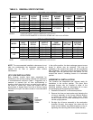
Both 80F & 120F Model furnaces are listed with the
Canadian Standards Association, (CSA), complies with
both Canadian and American (U.S.) standards for use
with No. 1 (Stove) and No. 2 (Furnace) Oil. Please refer
to the tables in the appendix for performance and
dimensional data.
DO NOT USE GASOLINE, CRANK CASE OIL,
OR ANY OIL CONTAINING GASOLINE.
In the United States of America, the installation of the
furnace and related equipment shall be installed in
accordance with the regulations of NFPA No. 31,
Installation of Oil Burning Equipment
, as well as in
accordance with local codes.
In Canada, the installation of the furnace and related
equipment shall be installed in accordance with the
regulations of CAN/CSA - B139, Installation Code For
Oil Burning Equipment, as well as in accordance with
local codes.
When installation or application questions arise,
regulations prescribed in the National Codes and Local
Regulations take precedence over the general
instructions provided with this installation manual. When
in doubt, please consult your local authorities.
All models are shipped assembled and pre-wired. The
furnace should be carefully inspected for damage when
being unpacked.
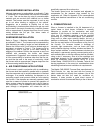
2. HEAT LOSS
To determine the correct furnace and firing rate for an
application, it is necessary to calculate the maximum
hourly heat loss of the building based on local design
conditions. In new construction, the heat loss should be
calculated on a room-by-room basis to enable proper
sizing of the trunk and branch ducts. In retrofit
applications, a building shell (overall) heat loss
calculation may be used.
In the United States, Manual J.
titled, "Load
Calculation" published by the Air Conditioning
Contractors of America, describes a suitable procedure
for calculating the maximum hourly heat loss.
In Canada, the maximum hourly heat loss may be
calculated in accordance with the procedures described
in the manuals of the Heating, Refrigeration and Air
Conditioning Institute of Canada (HRAI), or by other
method prescribed by authorities having jurisdiction that
are suitable for local conditions.
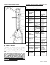
3. LOCATION OF UNIT
The furnace should be located such that the flue
connection to the chimney is short, direct and consists of
as few elbows as possible. When possible, the unit
should be centralized with respect to the supply and
return air duct work. A central location minimizes the
trunk duct sizing. All models may be installed on
combustible floors.
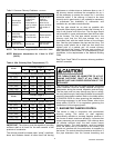
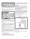
Minimum installation clearances are listed in Table 1.
Table 1: Clearance to Combustibles
HO-B – All Models
Location Up-flow Horizontal
Top 2 in. 2 in.
Bottom 0 in. 1 in.
S/A Plenum 1 in. 1 in.
Rear 1 in. 1 in.
Sides 1 in. 1 in.
Front 9 in.
1
9 in.
1
Flue Pipe 9 in. 9 in.
Enclosure Closet Alcove
1
24” clearance is required for servicing.
IMPORTANT:
SAVE THESE INSTRUCTIONS FOR FUTURE REFERENCE