


29733 R2 06/01/2003
8
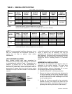
Table 2: Common Chimney Problems - continued
Key Trouble Diagnostic Remedy
K
Smoke pipe
extends into
chimney.
Measurement
of pipe from
within or
observation of
pipe by means
of a lowered
light.
Length of pipe
must be
reduced to
allow end of
pipe to be flush
with inside of
tile.
L
Failure to
extend the
length of flue
partition to the
floor.
By inspection
or smoke test.
Extend partition
to floor level.
M
Loose-fitted
clean-out door.
Smoke test.
Close all leaks
with cement.
NOTE: This furnace is approved for use with L-Vent.
NOTE: Maximum temperature for L-Vent is 575°F
(300°C).
Table 4: Min. Chimney Base Temperatures (°F)
Chimney Height (ft.)
Model
11 20 28 36
Chimneys with Thermal Resistance less than R6
80F (060) 300 400 535 725
80F (070) 275 340 430 535
80F (080) 270 330 405 505
120F (090) 260 320 380 475
120F (100) 250 300 355 430
120F (120) 225 300 365 430
Chimney Height (ft.)
Model
11 20 28 36
Chimneys with Thermal Resistance greater than R6
80F (060) 185 200 220 250
80F (070) 175 185 205 220
80F (080) 175 185 195 215
120F (090) 175 185 195 210
120F (100) 165 185 195 205
120F (120) 165 185 195 205
IMPORTANT: The chimney must be capable of providing
sufficient draft at all times for the safe removal of the
products of combustion.
The chimney should be tested under “winter” conditions;
doors and windows closed, all other fossil fuel burning
appliances on, clothes dryer on, bathroom fans on, etc. If
the chimney cannot overcome the competition for air, it
will be necessary to access the reason for it, and take
corrective action. If the chimney is found to be sized
correctly and in good repair, it will probably be necessary
to re-evaluate the availability of combustion and
ventilation air, and take corrective action.
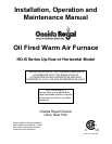
The flue pipe should be as short as possible with
horizontal pipes sloping upward toward the chimney at a
rate of one quarter inch to the foot. The flue pipe should
not be smaller in cross sectional area than the flue collar
on the furnace. The flue pipe should connect to the
chimney such that the flue pipe extends into, and
terminates flush with the inside surface of the chimney
liner. Seal the joint between the pipe and the lining. The
chimney outlet should be at least two feet above the
highest point of a peaked roof. All unused chimney
openings should be closed. Chimneys must conform to
local, provincial or state codes, or in the absence of local
regulations, to the requirements of the National Building
Code.
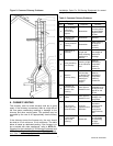
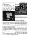
See Figure 2 and Table 3 for common chimney problems
and their remedies.
THE FURNACE MUST BE CONNECTED TO A FLUE
HAVING SUFFICIENT DRAFT AT ALL TIMES TO
ENSURE SAFE AND PROPER OPERATION OF THE
APPLIANCE.
The flue pipe must not be routed through concealed
space, because it must be visually checked for signs of
deterioration during the annual inspection and servicing.
The flue pipe must not pass through any floor or ceiling,
but may pass through a wall where suitable fire protection
provisions have been installed. Refer to the latest edition
of CAN/CSA B139 for rules governing the installation of
oil burning equipment. In the United States, refer to the
latest edition of NFPA 31 for regulations governing the
installation of oil burning equipment.
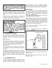
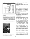
7. BAROMETRIC DAMPER CONTROL
This device is used in conjunction with conventional
chimney venting. This control (or draft regulator)
automatically maintains a constant negative pressure in
the furnace to obtain maximum efficiency. It ensures that
proper pressures are not exceeded. If the chimney does
not develop sufficient draft, the draft control cannot
function properly. The draft regulator, must be installed
within the same room or enclosure as the furnace, and
should not interfere with the combustion air supplied to
the burner. The control should be located a minimum of 3
flue pipe diameters from the furnace breeching and