


29733 R2 06/01/2003
6
NON-SUSPENDED INSTALLATION
Maintain clearances to combustibles as outlined in Table
1. Installation on a combustible floor requires a clearance
of 1 inch. This can be done by using a noncombustible
material such as one-inch thick channel iron or similar
material. The furnace must be supported in such a way
as to not allow twisting or sagging of the cabinet.
Suggestion; as a measure to prevent fuel oil from
accumulating in locations other than the fire pot, as could
be the case in the event of nozzle drip, install the furnace
with an approximate 2 degree slope from the oil burner
casing towards the fire pot. Use shims made of
noncombustible material.
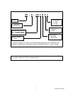
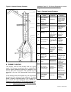
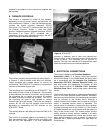
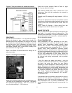
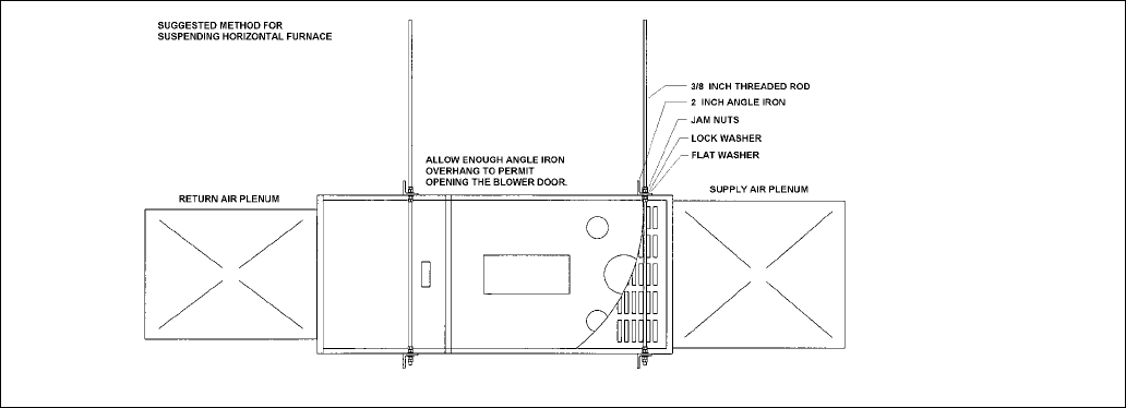
SUSPENDED INSTALLATION
Refer to Figure 1. Maintain clearances to combustibles
as outlined in Table 1. The furnace may be suspended by
field fabricating a cradle of angle iron and threaded rod.
Secure the furnace with 2 inch minimum slotted angle or
equivalent, as shown in Figure 1. The furnace must be
supported in such a way as to not allow twisting or
sagging of the cabinet. Position the supports so as to not
interfere with accessing the burner and blower
compartments. Suggestion; as a measure to prevent fuel
oil from accumulating in locations other than the fire pot,
as could be the case in the event of nozzle drip, install
the furnace with an approximate 2 degree slope from the
oil burner casing towards the fire pot.
4. AIR CONDITIONING APPLICATIONS
If the furnace is used in conjunction with air conditioning,
the furnace shall be installed in parallel with or upstream
from the evaporator coil to avoid condensation in the heat
exchanger. In a parallel installation, the dampers or air
controlling means must prevent chilled air from entering
the furnace. If the dampers are manually operated, there
must be a means of control to prevent the operation of
either system unless the dampers are in the full heat or
full cool position. The air heated by the furnace shall not
pass through a refrigeration unit unless the unit is
specifically approved for such service.
The blower speed must be checked and adjusted to
compensate for the pressure drop caused by the
evaporator coil. Refer to Appendix B for recommended
wiring and electrical connections of the air conditioning
controls.
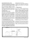
5. COMBUSTION AIR
When a furnace is installed in the full basement of a
typical frame or brick house, infiltration is normally
adequate to provide air for combustion and draft
operation. If the furnace is installed in a closet or utility
room, two (2) ventilation openings must be provided
connecting to a well ventilated space (full basement,
living room or other room opening thereto, but not a
bedroom or bathroom). One opening shall be located 6"
from the top and bottom of the enclosure at the front of
the furnace. For furnaces located in buildings of
unusually tight construction, such as those with high
quality weather stripping, caulking, windows and doors, or
storm sashed windows, or where basement windows are
well sealed, a permanent opening communicating with a
well ventilated attic or with the outdoors shall be provided,
using a duct if necessary. Size all of the openings and
associated ductwork by the standards provided in the
latest Oil Installation Code editions; NFPA 31 in the
United States, CAN/CSA B139 in Canada. Take all fuel
burning appliances in the area into consideration when
calculating combustion and ventilation air requirements.
The Model CAS-2B-90E Furnace Boot manufactured by
Field Controls, Inc. may be used with the furnace to
obtain combustion air directly from outdoors. Use of this
device does not alter the need for ventilation air;
however, it does provide a good direct source of
combustion air and is connected directly to the oil burner.
Figure 1: Typical Suspended Application