


29733 R2 06/01/2003
10
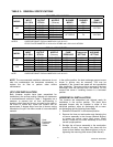
The power requirements for the HO-B Series models are:
120 VAC, 1 Æ, 60 Hz., 12A. 5-ton models: 120 VAC, 1 Æ,
60 Hz., 16A.
Accessories requiring 120 VAC power sources such as
electronic air cleaners and humidifier transformers may
be powered from the ST9103 EFT. Do not use the direct
drive motor connections as a power source, since there
is a high risk of damaging the accessories by exposure to
high voltage from the auto-generating windings of the
direct drive motor.
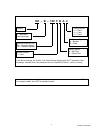
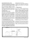
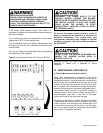
Thermostat wiring connections and air conditioning
contactor low voltage connections are shown in the wiring
diagrams. Some micro-electronic thermostats require
additional controls and wiring. Refer to the thermostat
manufacturer's instructions.
The thermostat should be located approximately 5 feet
above the floor, on an inside wall where there is good
natural air circulation, and where the thermostat will be
exposed to average room temperatures. Avoid locations
where the thermostat will be exposed to cold drafts, heat
from nearby lamps and appliances, exposure to sunlight,
heat from inside wall stacks, etc.
Normal heat anticipator setting: 0.1 A. For more precise
adjustment, the heat anticipator may be adjusted to the
amperage draw of the heating control circuit as
measured between the "R" and "W" terminals of the
thermostat. To reduce the risk of damaging the heat
anticipator, do not measure circuit without first removing
one of the two wires first. To determine the heating circuit
amperage draw:
1. Disconnect one of the “R” or “W” wires from the
thermostat terminal.
2. Connect an ammeter between the wire and the
thermostat terminal to which it was attached.
3. Note the amperage reading when the heating
contacts are closed. (System switch must be on
“
HEAT” if so equipped.
4. Re-connect the thermostat wire. If the thermostat is
serving a combination heating and air conditioning
system, pay particular attention to polarity.
5. When the thermostat is reconnected and re-
plumbed, adjust the heat anticipator setting to match
the observed amperage reading.
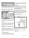
10. HUMIDIFIER
A humidifier is an optional accessory available through
most heating supplies outlets. Installation should be
carried out in accordance with the humidifier
manufacturer's installation instructions. Water or water
droplets from the humidifier should not be allowed to
come into contact with the furnace heat exchanger.
Terminals (115 v) are provided on the ST9103 EFT
control. Do not use direct drive motor connections as a
source of power for 120 VAC humidifiers and humidifier
transformers.
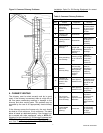
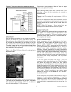
11. OIL TANK
Oil storage tanks must be selected and installed in
compliance with applicable codes; in the United States,
NFPA 31, Standard for the Installation of Oil Burning
Equipment, Chapter 2. Observe all local codes and by-
laws. And in Canada, CAN/CSA-B139, Installation Code
for Oil Burning Equipment, Section 6
In general, the oil tank must be properly supported and
remain stable in both empty and full condition. The oil
tank must be fitted with vent and supply pipes to the
outdoors. Refer to the above-mentioned codes for sizing.
The vent pipe must be no less than 1¼ inches I.P.S., and
terminate with an appropriate vent cap in a location
where it will not be blocked. The fill pipe must be no less
than 2 inches I.P.S., and terminate with an appropriate
cap in a location where debris will not enter the fill pipe
during oil delivery.
If located indoors, the tank should normally be in the
lowest level, (cellar, basement, etc.). It must be equipped
with a shut-off valve at the tank outlet used for the oil
supply. The oil tank must be located as to not block the
furnace / room exit pathway. Observe all clearances
specified in the above-mentioned codes.
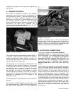
12. PIPING INSTALLATION
In the United States the installation must be in
accordance with the requirements of NFPA No. 31 and
local codes and regulations.
In Canada, the entire fuel system should be installed in
accordance with the requirements of CAN/CSA B139,
and local regulations. Use only approved fuel oil tanks
piping, fittings and oil filters.
Ensure that all fittings used in a copper oil line system are
high quality flare fittings. Do not use compression fittings
.
Do not use Teflon tape on any fittings.
Pressurized or gravity feed installations must not exceed
3 PSIG. Pressures greater than 10 PSIG may cause
damage to the shaft seal. If the height of the oil stored in
a tank above the oil burner exceeds 11½ feet, it may be
necessary to use a pressure-regulating device approved
for this purpose.