


29733 R2 06/01/2003
5
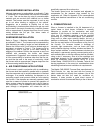
NOTE: The recommended installation clearances do not
take into consideration the clearances necessary to
replace the air filter or perform other routine
maintenance.
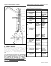
UP-FLOW INSTALLATION
Both furnaces models have been assembled for
installation in the up-flow position. Maintain all clearances
to combustibles as outlined in Table 1. Suggestion; as a
measure to prevent fuel oil from accumulating in
locations other than the fire pot, as could be the case in
the event of nozzle drip, install the furnace with an
approximate 2 degree slope from the oil burner casing
towards the fire pot. Use shims made of noncombustible
material.
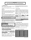
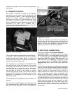
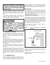
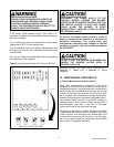
In the upflow position, the heat exchanger support screw
shown in picture may be removed. This may be
preferable if the furnace rear panel will be inaccessible
after installation. The screw must be removed if the heat
exchanger must be removed from the cabinet. Do not
remove this screw if installing furnace in a horizontal
position.
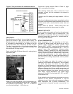
HORIZONTAL INSTALLATION
The furnaces are assembled and shipped ready for
installation in the up-flow position. The direct drive
equipped furnace may be installed in either of the
horizontal positions; warm air discharging left or warm
air-discharging right by following these steps:
1. Rotate the furnace 90° to the desired position.
2. Remove the three nut and washer sets fastening the
oil burner assembly to the furnace (Beckett Burner)
or loosen the burner mount Allen screw (Riello
burner). Rotate the oil burner assembly to be in the
normal upright position.
3. Re-align the oil burner assembly to the combustion
chamber (fire-pot), then secure into place with the
three nut and washer sets (Beckett burner) or by re-
tightening the mounting Allen screw (Riello burner).
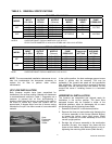
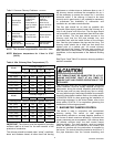
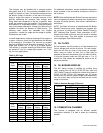
TABLE 2.: GENERAL SPECIFICATIONS
BECKETT AFG BURNER
MODEL
INPUT
U.S. GPH
OUTPUT
BTU/Hr.
NOZZLE
(Delavan)
BURNER
MODEL
BURNER
HEAD
PUMP
PRESSURE
0.50 58
,
100 0.50 / 70° W
A
F76BO F0
0.65 68
,
000 0.65 / 70° W
A
F76BN F3
80F
0.70 78
,
900 0.70 / 70° W
A
F76BN F3
100 PSIG
0.75 87
,
700 0.75 / 70° W
0.85 98
,
800 0.85 / 70° W
120F
1.00 113
,
400 1.00 / 70° W
AF76BZHS F4 100 PSIG
NOTES: OVER-FIRE DRAFT FOR ALL MODELS IS -0.02 IN. W.C.
STATIC PLATE DIAMETER: 3-3/8 inch for AF76BO and 2-3/4 inch for AF76XN.
RIELLO 40F3 BURNER
MODEL
INPUT
U.S. GPH
OUTPUT
BTU/Hr.
NOZZLE
(Delavan)
PUMP
PRESSURE
T
URBULATOR
SETTING
AIR BAND
SETTING
0.50 58
,
000 0.40 / 60°W 160 PSIG 1.5 2.25
0.60 73
,
000 0.50 / 60°W 150 PSIG 1.5 2.5
80F
0.70 79
,
000 0.60 / 60°W 145 PSIG 2.0 3.0
0.75 87
,
000 0.60 / 60°W 150 PSIG 2.0 3.5
0.85 100
,
000 0.70 / 60°W 150 PSIG 2.5 4.0
120F
0.95 112
,
000 0.75 / 60°W 160 PSIG 3.0 6.0
NOTE: OVER-FIRE DRAFT FOR ALL MODELS IS -0.02 IN. W.C.
Heat
Exchanger
Support
Screw