


29733 R2 06/01/2003
20
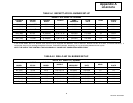
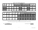
TABLE A-5 BELT DRIVE BLOWER SET-UP
Blower Set-Up Model
HO-B
0.20 in. w.c. 0.50 in. w.c.
Cooling Capacity
Pulley Pulley
Bonnet Output
(BTUH)
Blower
Motor
hp
Fan Belt
Blower Motor Turns Out Blower Motor Turns Out
Tons CFM Range
80 (60,000) 3 2
80 (70,000) 2 1
80 (80,000)
G10 ½ 4L360 5 x ¾ 3¼ x ½
2
5 x ¾ 3¼ x ½
1
3 1000 - 1300
120 (90,000) 3 2
120 (100,000) 3 1
120 (120,000)
G10 ½ 4L360 5 x ¾ 3¼ x ½
2
5 x ¾ 3¼ x ½
0
3 1000 - 1500
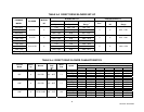
TABLE A-6 BELT DRIVE BLOWER CHARACTERISTICS
CFM
External Static Pressure - inches w.c.
Furnace
Model
Motor
hp
Blower
Temp.
Rise
(DT)
Motor
FLA
Motor
Pulley
Turns Out
0.20 0.30 0.40 0.50 0.60 0.70
0 1596 1518 1435 1330 1247 1184
1 1505 1434 1347 1220 1081 993
2 1567 1453 1291 1125 996 817
80F ½ G10 60° - 90°F 5.8
3 1429 1332 1180 1064 818 558
0 1832 1747 1658 1546 1446 1338
1 1694 1603 1507 1382 1245 1119
2 1566 1467 1339 1196 1064 880
120F ½ G10 55° - 85°F 5.8
3 1383 1270 1120 1006 771 545
TIP:
These formulae will assist with the design of the ductwork and the determination of airflow delivery:
() ()
CFM
Bonnet Output
x SystemTem perature R ise
SystemTemperature Rise
Bonnet Output
xCFM
= =
1085 1085. .