


UltraGlow G36D Zero Clearance Direct Vent Gas Fireplace 7
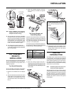
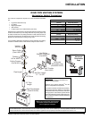
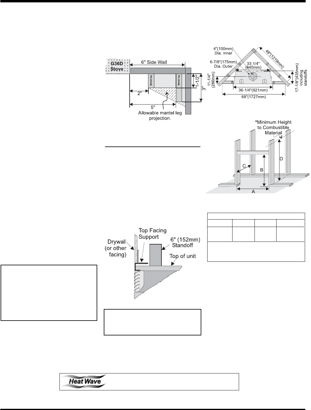
MANTEL LEG
CLEARANCES
Combustible mantel leg clearances as per
diagram below:
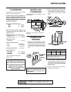
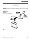
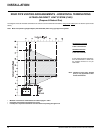
FRAMING AND
FINISHING
1) Determine the total thickness of facing
material (e.g. drywall plus ceramic tiles) to
allow the fi nished surface to be fl ush with
the front of the unit. Total facing thickness
can vary from 1/2" (13mm) to 1-1/4" (32mm)
thick.
Maximum 1-1/2" projection at 2" minimum
clearance.
2) Frame in the enclosure for the unit with
framing material. The framed opening is
37-1/4" high x 36-1/4" wide x 17-3/8" deep
(946mm high x 921mm wide x 441mm
deep).
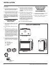
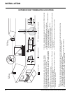
CLEARANCES
The clearances listed below are Minimum
distances unless otherwise stated:
A major cause of chimney related fi res is
failure to maintain required clearances (air
space) to combustible materials. It is of the
greatest importance that this fi replace and
vent system be installed only in accordance
with these instructions.
Clearance to Combustibles from:
Back 0" (0mm)
Side 0" (0mm)
Floor 0" (0mm)
NOTE: The minimum fl oor clearance must
be maintained from the top surface of the
carpeting, tile, etc.
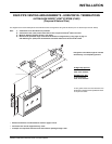
Minimum Clearance from Top of Unit to:
Mantel* Minimum 7" (177mm)
Ceiling from top of unit. 32" (1016mm)
Side Wall Clearance
Flush Front 6" (152mm)
Horizontal Vent Clearances
Top 2-1/2" (64mm)
Side 1-1/2" (38mm)
Bottom 1-1/2" (38mm)
Vertical Vent Clearances 1-1/4" (32mm)
Alcove Clearances**:
Max. Depth 36" (914mm)
Min. Width 48" 1219mm)
Min. Height 72" 1829mm)
* see mantle clearance instructions
(pages 7 & 8).
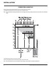
INSTALLATION
3) For exterior walls, insulate the enclosure to
the same degree as the rest of the house,
apply vapour barrier and drywall, as per lo-
cal installation codes. (Do not insulate the
fi replace itself.)
4) The top of the unit must not be closer than
32" (813mm) to the ceiling.
WARNING:
Fire hazard is an extreme risk if
these clearances are not adhered to.
It is of greatest importance that this
fi replace and vent system be
installed only in accordance with
these instructions.
Install Side Nailing Strips, Top Facing
Support, and Top Standoffs before unit is
slipped into position. See page 9 for as-
sembly details.
The HeatWave Duct Kit has different clearance and framing
requirements, check the HeatWave manual for details.
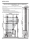
Framing Dimensions
A B C D
36-1/4" 37-1/4" 17-3/8" 46-1/2"*
921mm 946mm 441mm 1181mm*
* 'D' is Minimum height to combustible materi-
als including the Minimum 2-1/2" (64mm) Top
clearance to the Horizontal Vent.