


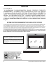
UltraGlow G36D Zero Clearance Direct Vent Gas Fireplace
6
INSTALLATION
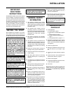
Diagram 1
This includes:
1) Clocking the appliance to ensure the correct
fi ring rate (rate noted on label 26,000 Btu/h)
after burning appliance for 15 minutes.
2) If required, adjusting the primary air to ensure
that the fl ame does not carbon. First allow
the unit to burn for 15-20 min. to stabilize.
CAUTION: Any alteration to the product that
causes sooting or carboning that results
in damage is not the responsibility of the
manufacturer.
LOCATING YOUR
GAS STOVE
1) When selecting a location for your stove,
ensure that the clearances outlined on this
page are met.
2) Provide adequate clearances for servic-
ing.
3) The appliance must be installed on a fl at,
solid, continuous surface (e.g. wood, metal,
concrete). This may be the fl oor, or raised up
on a platform to enhance its visual impact.
If the appliance is going to be installed on
carpeting, combustible linoleum tile or other
combustible material other than wood fl oor-
ing, the appliance must be installed on a
metal or wood panel extending the full width
and depth of the appliance.
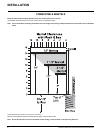
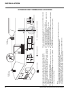
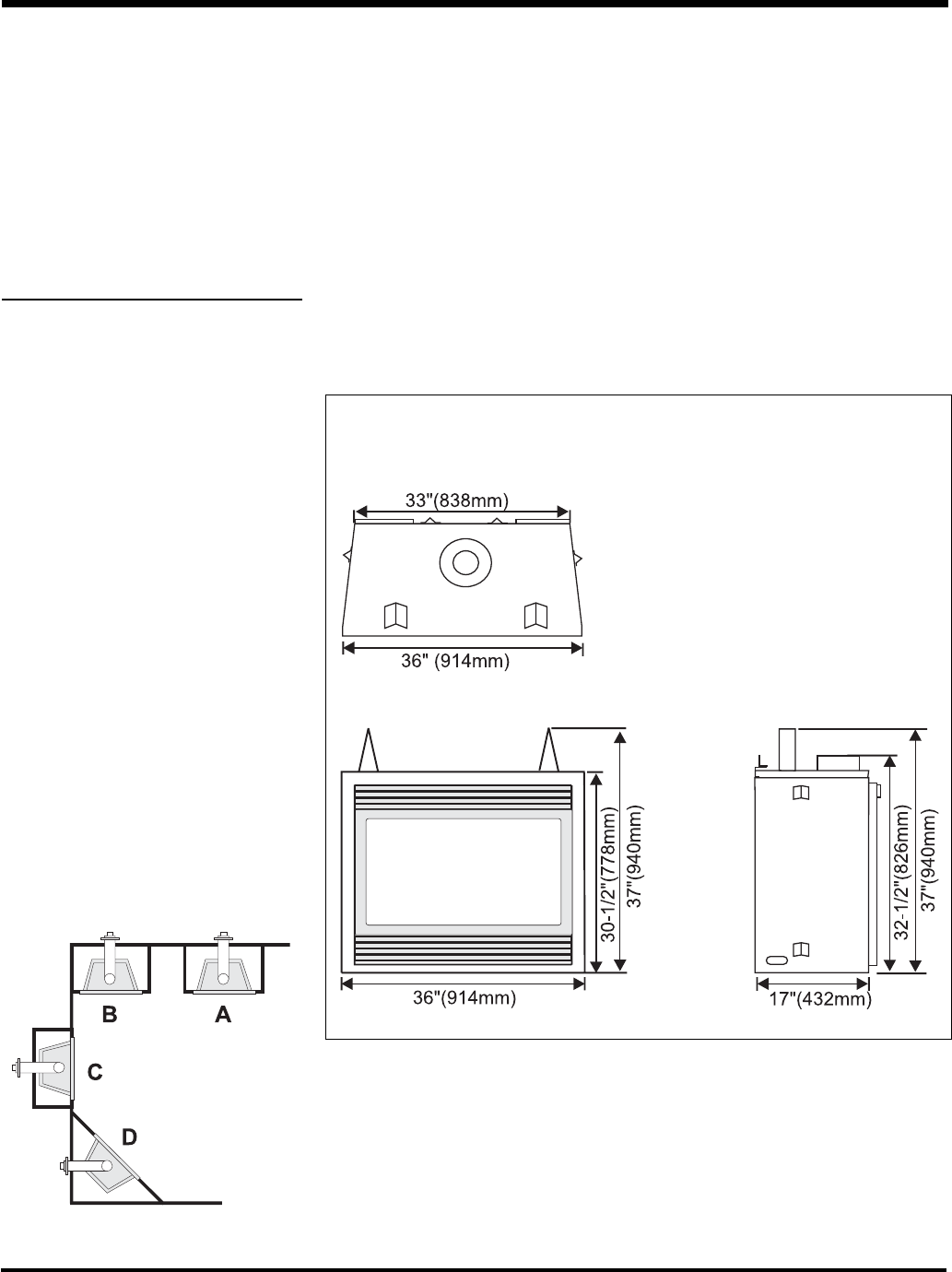
4) The G36D Direct Vent Gas Fireplace can be
installed in a recessed position or framed out
into the room as in A, B, C, D. See Diagram
1.
A) Flat on Wall
B) Flat on Wall Corner
C) Recessed into
Wall/Alcove
D) Corner
5) This appliance is Listed for bedroom instal-
lations when used with a Listed Millivolt
Thermostat. Some areas may have further
requirements, check local codes before
installation.
6) The G36D Direct Vent Gas Fireplace is
approved for alcove installations, which
meet the clearances listed on this page.
7) We recommend that you plan your instal-
lation on paper using exact measurements
for clearances and fl oor protection before
actually installing this appliance. Have a
qualifi ed inspector, dealer, or installer review
your plans before installation.
Note: For vent terminations see page 10.
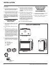
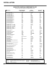
G36D UNIT DIMENSIONS
MANUFACTURED
MOBILE HOME
ADDITIONAL
REQUIREMENTS
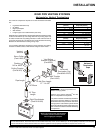
1) Ensure that structural members are not cut
or weakened during installation.
2) Ensure proper grounding using the #8
ground lug provided. See page 29.