


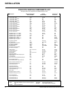
UltraGlow G36D Zero Clearance Direct Vent Gas Fireplace
20
Diagram 4
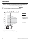
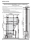
6) The arrow on the vent cap should
be pointing up. Insure that the 1-1/2"
clearances to combustible materials
are maintained (Diagram 4). Install the
termination cap.
NOTE: For Snorkel terminations in ABOVE
grade installations, follow national
or local code requirements.
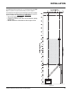
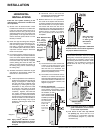
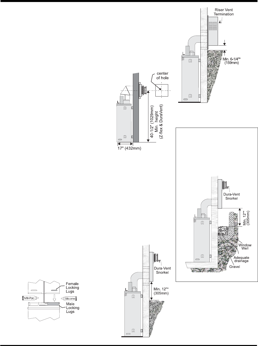
Below Grade Installation
If the Snorkel Termination must be installed
below grade, i.e. basement application, proper
drainage must be provided to prevent water
from entering the Snorkel Termination. Refer
to Diagram 4. Do not attempt to enclose the
Snorkel within the wall, or any other type of
enclosure.
*Diagrams 3 & 4: As specifi ed in CGA B149
Installation Code. Local codes or regulations
may require different clearances.
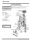
HORIZONTAL
INSTALLATIONS
Install the vent system according to the
manufacturer's instructions included with
the components.
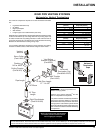
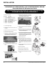
1) Set the unit in its desired location. Check
to determine if wall studs or roof rafters are
in the way when the venting system is at-
tached. If this is the case, you may want to
adjust the location of the unit. Rough in the
gas preferably on the right side of the unit
and the electrical (junction block is on the
left side) on the left.
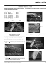
2) Direct Vent pipe and fi ttings are designed
with special twist-lock connections to con-
nect the venting system to the appliance
fl ue outlet. A twist-lock appliance adaptor
is an available option that must be used in
conjunction with the Simpson Dura-Vent
Direct Vent GS system.
3) Put a bead of silicone inside the outer sec-
tion of the adapter and a bead of Mill Pac
on the inner collar. Slip the adapter over the
existing inner and outer fl ue collar and fasten
to the outer collar only with the 3 supplied
screws (drilling pilot holes will make this
easier). Level the fi replace and fasten it to
the framing using nails or screws through
the nailing strips.
4) Assemble the desired combination of pipe
and elbows to the appliance adaptor and
twist-lock for a solid connection.
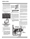
Note:
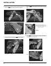
a) Twist-lock procedure: Four indentations,
located on the female ends of pipes and
fi ttings, are designed to slide straight
onto the male ends of adjacent pipes
and fi ttings, by orienting the four pipe
indentations so they match and slide
in to the four entry slots on the male
ends, Diagram 1. Push the pipe sections
completely together, then twist-lock
one section clockwise approximately
one-quarter turn, until the two sections
are fully locked. The female locking lugs
will not be visible from the outside, on
the Black Pipe or fi ttings. They may be
located by examining the inside of the
female ends.
Diagram 1
b) Horizontal runs of vent must be
supported every three feet. Wall straps
are available for this purpose.
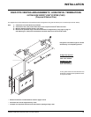
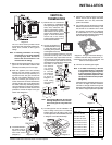
5) Mark the wall for a 10" x 10" square hole.
The center of the square hole should line
up with the centerline of the horizontal pipe.
Cut and frame the 10 inch square hole in
the exterior wall where the vent will be
terminated. If the wall being penetrated is
constructed of non-combustible material, i.e.
masonry block or concrete, a 7"(178mm)
dia. (7-1/2"(191mm) dia. for fl ex) hole is
acceptable.
Diagram 2
Note:
a) The horizontal run of vent must be level,
or have a 1/4 inch rise for every 1 foot
of run towards the termination. Never
allow the vent to run downward. This
could cause high temperatures and may
present the possibility of a fi re.
b) The location of the horizontal vent ter-
mination on an exterior wall must meet
all local and national building codes, and
must not be blocked or obstructed. For
External Vent Terminal Locations, see
diagram on page 10.
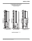
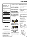
c) Snorkel Terminations:
For installations requiring a vertical rise
on the exterior of the building, 14-inch
and 36-inch tall Snorkel Terminations
are available, as well
as the standard Riser
Vent. Follow the same
installation procedures
as used for stand-
ard Horizontal
Termination.
NEVER
install the
snorkel
upside
down.
Diagram 3
Diagram 3a
Note: Riser Vent
is only for use
in above grade
terminations.
Note: Apply sealant "Mill-Pac" to inner
pipe and high temperature silicone
sealant to outer pipe on every twist-
lock joint.
Note: With Dura-Vent,
the mini-
mum height
is achieved
by installing
a 90
o
elbow
directly to
the rigid pipe
adaptor.
INSTALLATION