


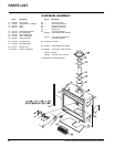
UltraGlow G36D Zero Clearance Direct Vent Gas Fireplace 35
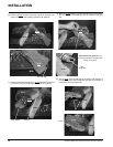
13) Undo the pilot tube from the valve with a
7/16" wrench.
14) Undo the quick drop out thermocouple nut
on the valve with a 9mm (metric) wrench.
15) Remove the Piezo ignitor wire and push
button assembly.
16) Undo the "gas out" fl are nut with a 13/16"
wrench.
17)
Undo the "gas out" fl are fi tting with an 11/16"
wrench.
18) Remove the 4 Phillips head screws from
the sides of the valve bracket and remove
valve.
Hint: If you are using black pipe, ensure
that there is a union by the valve,
otherwise removal will be almost
impossible.
INSTALLING VALVE
1) Attach the valve to the valve bracket with
the 4 (m5x8 metric) screws provided.
2) Reconnect the "gas out" fl are fi tting with an
11/16" wrench.
3) Reconnect the "gas out" fl are nut with a
13/16" wrench.
4) Install piezo ignitor push button assembly
and reconnect wire.
5) Reconnect the quick drop out thermocouple
nut with a 9mm wrench.
6) Reconnect the pilot tube nut with a 7/16"
wrench.
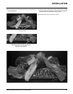
7) Scrape off the old gasket from the fl oor of the
fi rebox and from the valve tray assembly.
8) Install a new gasket and reinstall the valve
tray assembly.
Note: Failure to install a new gasket may
severely affect the appliance per-
formance.
9) Reinstall the 12 hold down screws.
10) Hook up the 2 TP and 2 TH wires to the
appropriate connections on the valve.
11) Reinstall the bottom brick panel and the
front log stand.
12) Install burner assembly
13) Hook up the gas line and check for gas
leaks with a soap and water solution or a
gas leak detector. (Do not use open fl ame
for leak testing.)
14) Fire up the unit temporarily
15) Check the manifold pressure.
16) Reinstall the logs and base panels as
needed.
17) Close the door and replace the louvers.
18) Fire up the unit again and check for proper
fl ame appearance and glow on logs.
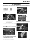
REMOVING VALVE
1) Shut off the gas supply.
2) Remove louvers.
3) Open and remove the fl ush door.
4) Remove logs.
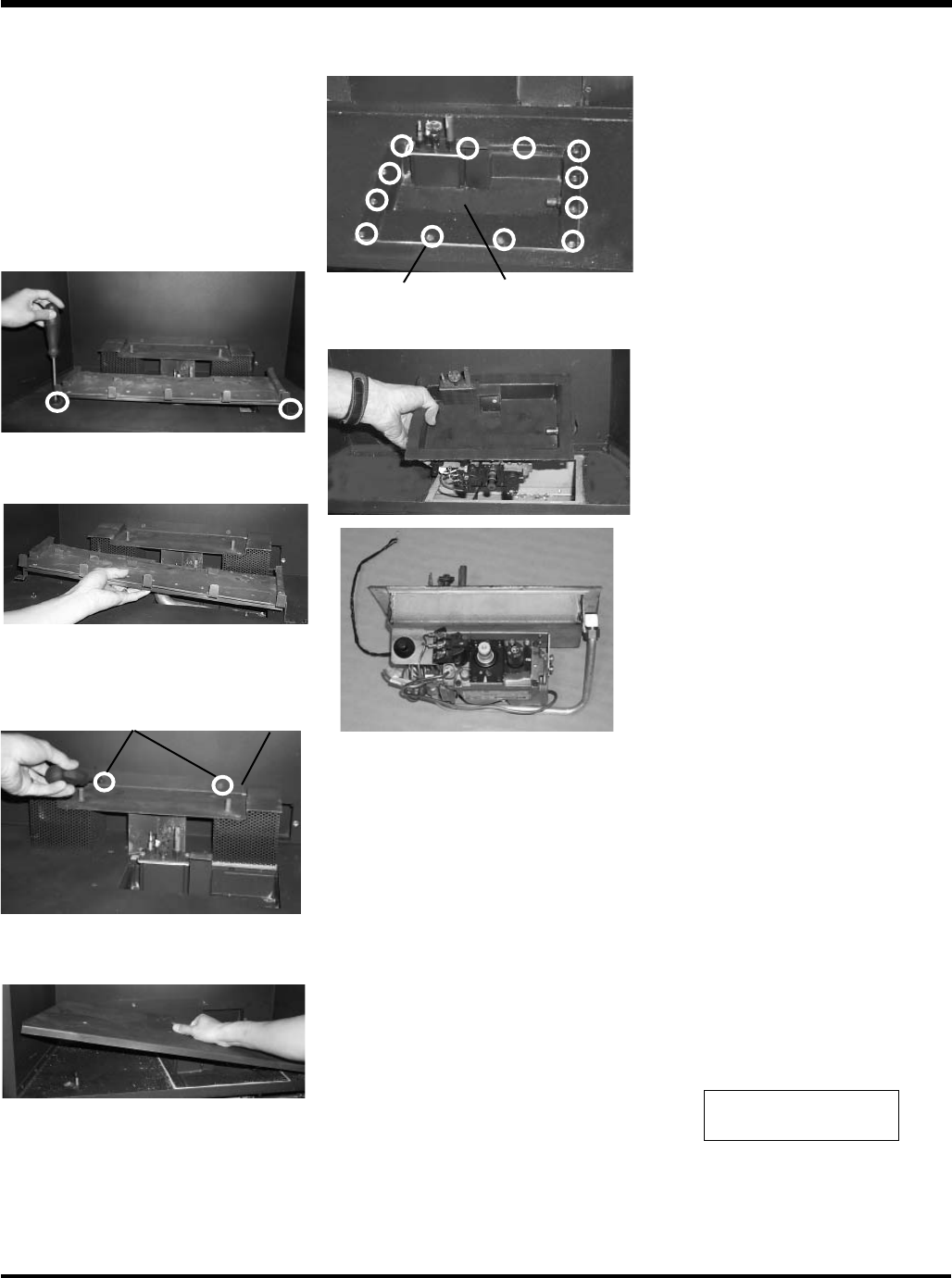
5) Remove the burner assembly by removing
the two Phillips head screws.
6) Remove the burner assembly by sliding left
and out.
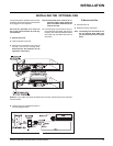
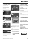
Rear Log Stand
Screws
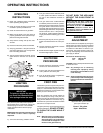
11) Remove the 12 Phillips head screws securing
the valve tray assembly in place.
7) Remove the rear log stand by removing the
2 screws.
MAINTENANCE
screws
Valve Tray Assembly
8) Lift out the bottom base panel.
9) Disconnect the inlet gas line.
10) Disconnect the 2 TP wires and the 2 TH
wires from the valve.
12) Lift the entire assembly out.
Verify proper operation
after servicing.