5100-I ACT WOOD INSERT
R
438-0380E
April 21, 2010
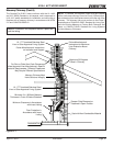
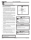
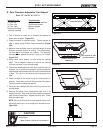
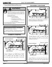
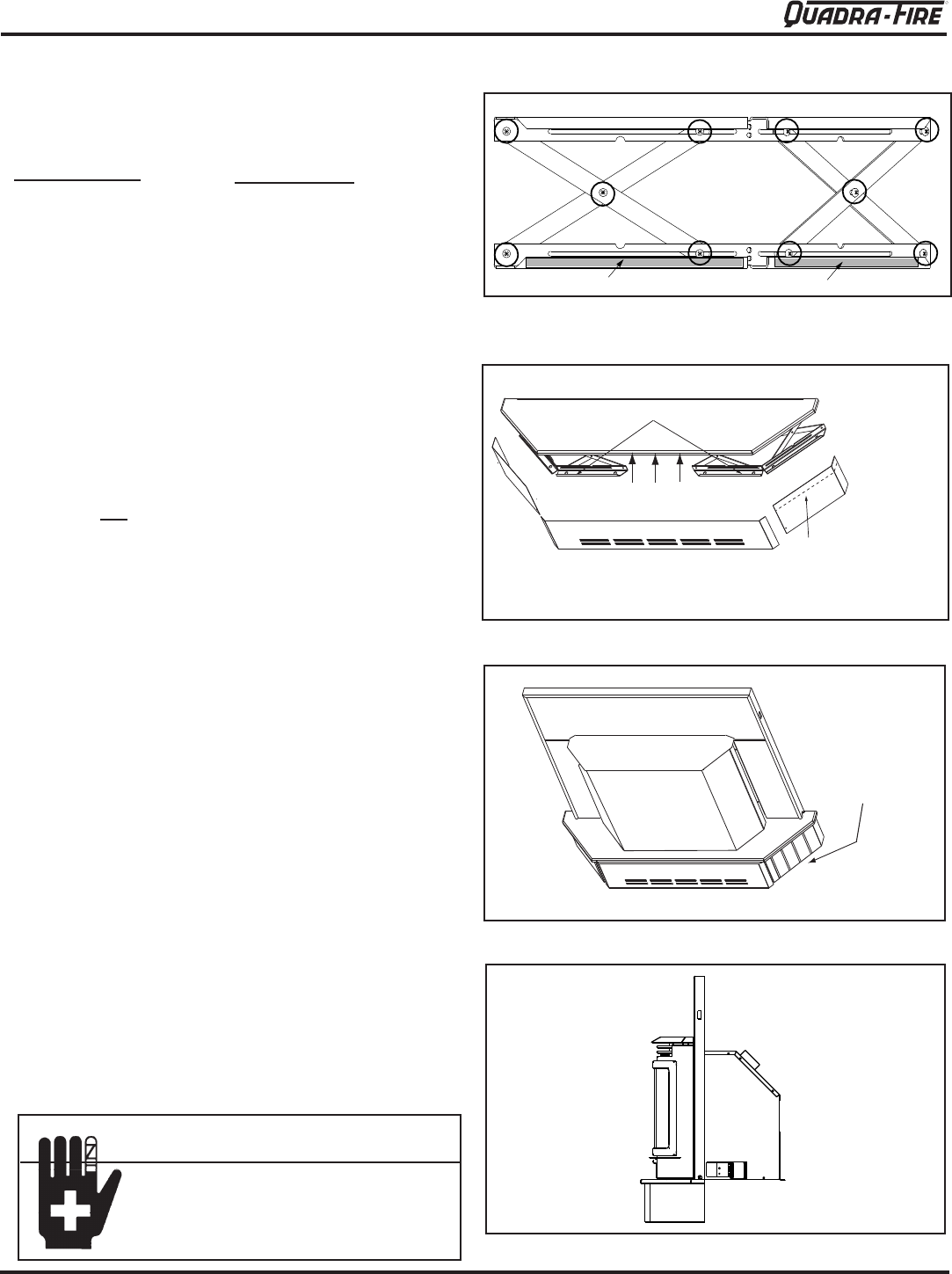
Figure 23.1
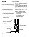
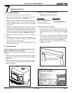
Figure 23.2
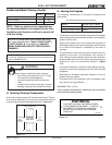
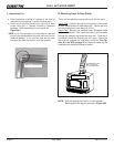
Figure 23.3
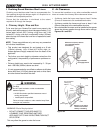
Figure 23.4
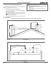
E. Zero Clearance Adjustable Trim Support
Size: 12” d x 50” w, 2-10” h
loose when shipped. Figure 23.1.
Figure
23.2.
-
rial from top
be sharp; wear gloves to prevent injury to your hands.
Figure 23.2.
for some variance in your straight edge.
scissors has a particularly powerful bonding adhesive.
tape.
and set aside.
8. Remove the paper from double-sided tape that is to
accept trim side. Align side and then press hard against
tape to secure side piece. Repeat for other side. Install
front trim piece last.
NOTE
Figure 23.3.
Included in Kit:
(
Double-sided tape
(already installed)
Tools Needed:
Measuring tape
Gloves
INSTALL FRONT TRIM LAST.
CORNERS OVERLAP SIDE
TRIM PIECES
EXPAND SCISSORS TO DESIRED HEIGHT
CUT TOP EDGE OF TRIM,
NOT BOTTOM EDGE
Decorative tile may
be installed
CAUTION
• Wear protective gloves during installation.
DOUBLE-SIDED TAPE
DOUBLE-SIDED TAPE
SCREWS ARE CIRCLED
EXPLODED VIEW OF SCISSORS


