5100-I ACT WOOD INSERT
R
438-0380E
April 21, 2010
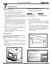
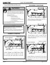
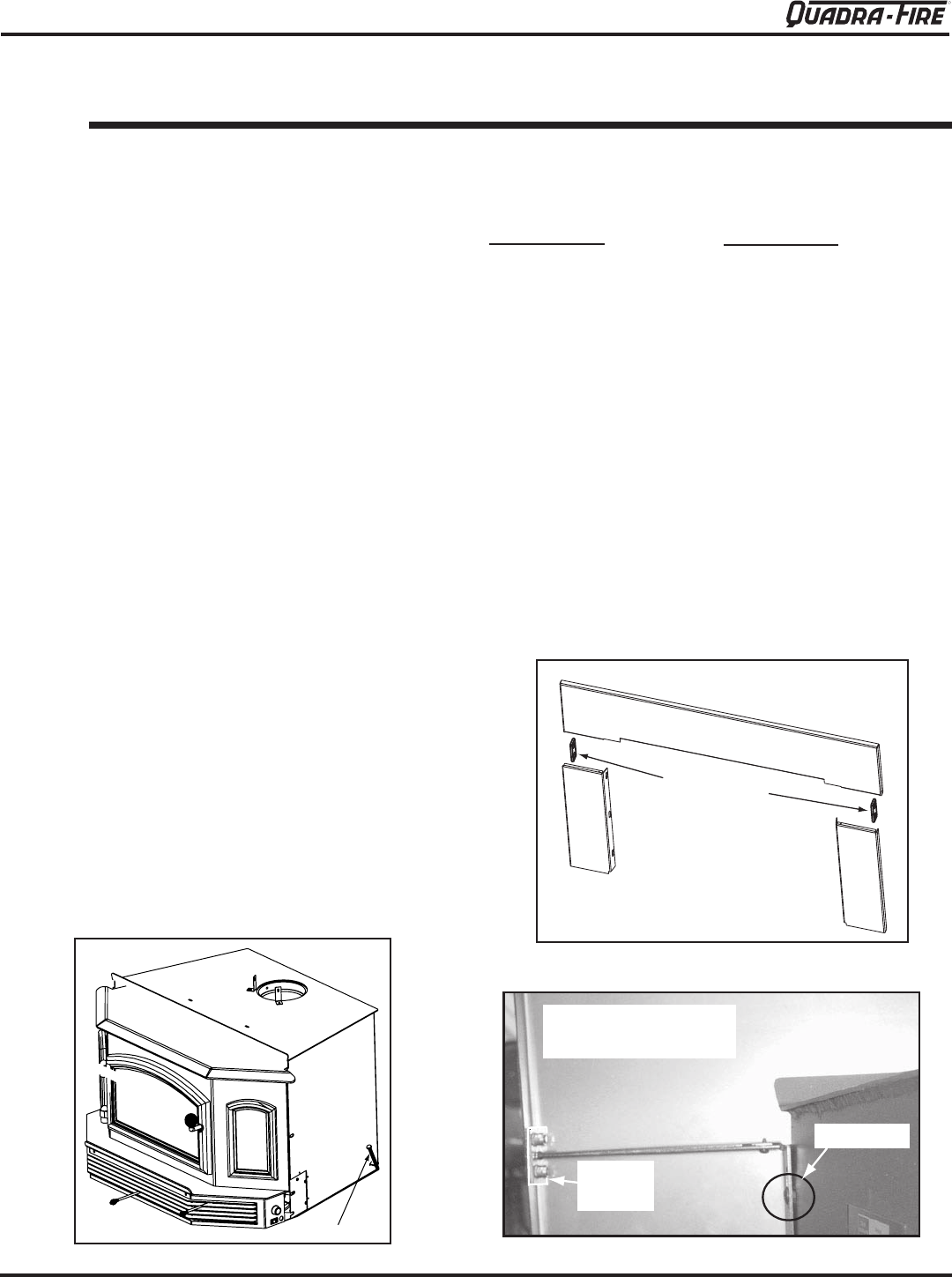
Figure 21.1
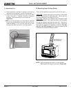
Figure 21.2
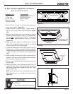
Figure 21.3
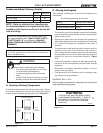
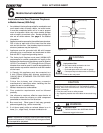
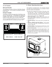
Two leveling bolts, 3/8” x 4” are shipped inside the com-
ponent pack found inside the rebox.
NOTE:-
ing bolts.
into weld nuts welded to each side of the insert bottom
Figure 21.1.
-
ward to level insert.
B. Leveling Bolts
7
Appliance Set-up
Do not tighten sides until
top is locked into place
Panel brackets
a.
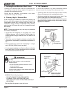
Loosely install the 2 side panels, do not tighten, using
the cage nuts already attached to the appliance.
Figure
21.3.
Figure 21.2.
handle screw driver.
Back view of top and
side panel assembled
Panel
bracket
Cage nut
1. Attaching Panels to the Insert
C. Panel & Trim Set Installation
Kit Includes:
(
Tools Needed:
A. Installation Outline
start the bolts in the weld nuts. Figure 21.1.
-
ing leaving approximately 4 inches (102mm) protruding
out the front.
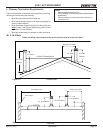
4. Assemble the panels and temporarily attach to insert.
-
opening and that the face can be sealed off from room
air when installation is complete. Figures 21.2 & 21.3.
5. Remove the panels and secure liner to the chimney
ring.
then secure liner to offset adapter.
,EVELING"OLT


