


26 Pelco Manual C1043M-A (2/96)
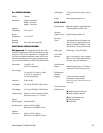
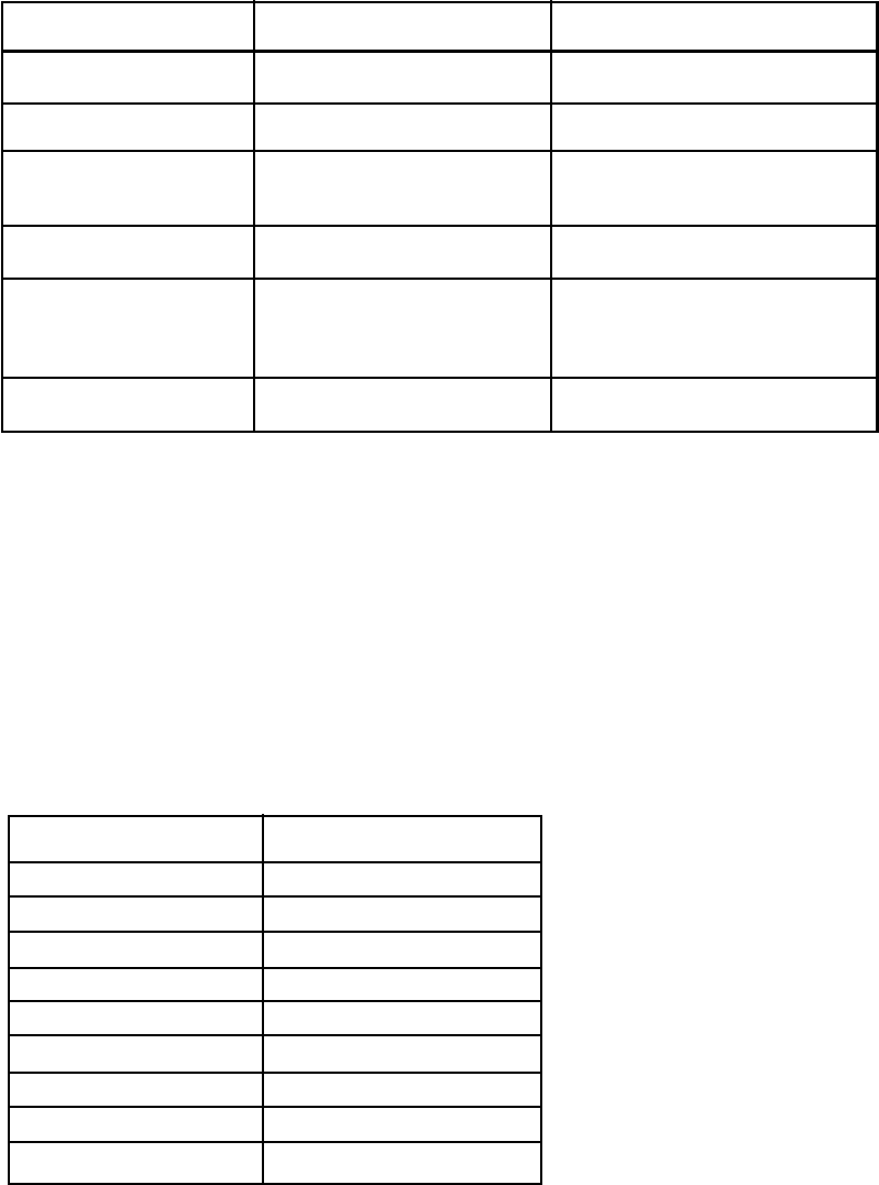
9.1 OUTPUT DEFINITIONS
WIRE COLOR PIN DESIGNATION DESCRIPTION
White 1 +5 volts (For testing only)
Black 2 Signal Ground
Red 3 RS232 Current Loop
CHANNEL 1 INPUT
Green 4 NOT USED
Yellow 5 (Opto y-jack input)
ICI1000PIM Input for
CHANNEL 1
Blue 6 NOT USED
AUXILIARY PORT 1 (Printer Port)
Communications = Standard RS232 Asynchronous
9600 Baud
8 bits
No Parity
AUXILIARY PORT 2 (Shadow Switcher/Dome Port)
Communications = Standard RS232 Asynchronous
9600 Baud
8 Bits
No Parity
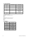
9.2 DB9 PINOUT
PIN # DESCRIPTION
1 NOT USED
2 RX AUX 1
3 (Printer port) TX AUX 1
4 NOT USED
5SIGNAL GROUND
6 NOT USED
7 RX AUX 2
8 (Dome-Shadow port) TX AUX 2
9 NOT USED