


6
OM5-II
Analog Current Input Modules
FEATURES
● ACCEPTS MILLIAMP LEVEL SIGNALS
● HIGH LEVEL VOLTAGE OUTPUTS
● 1500Vrms TRANSFORMER ISOLATION
●
ANSI/IEEE C37.90.1-1989 TRANSIENT PROTECTION
● INPUT PROTECTED TO 240VAC CONTINUOUS
● 160dB CMR
● 95dB NMR AT 60Hz, 90dB AT 50Hz
● ±0.05% ACCURACY
● ±0.02% LINEARITY
● CSA CERTIFIED, FM APPROVED, CE COMPLIANT
● MIX AND MATCH OM5 TYPES ON BACKPANELS
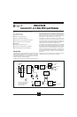
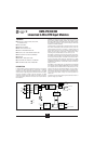
DESCRIPTION
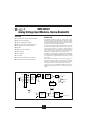
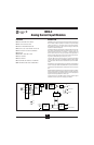
Each OM5-II current input module provides a single channel of analog input
which is filtered, isolated, amplified, and converted to a high level analog
voltage output (Figure 1). This voltage output is logic switch controlled,
which allows these modules to share a common analog bus without the
requirement of external multiplexers.
The OM5-II modules are designed with a completely isolated computer side
circuit which can be floated to ±50V from Power Common, pin 16. This
complete isolation means that no connection is required between I/O
Common and Power Common for proper operation of the output switch. If
desired, the output switch can be turned on continuously by simply connect-
ing pin 22, the Read-Enable pin to I/O Common, pin 19.
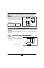
A precision 20Ω current conversion resistor is supplied with the OM5-II
module. Sockets are provided on the OM5-BP backpanels to allow installa-
tion of this resistor. Extra resistors are available under part number OMX-
1362-C.
Signal filtering is accomplished with a six-pole filter which provides 95dB of
normal-mode rejection at 60Hz and 90dB at 50Hz. Two poles of this filter are
on the field side of the isolation barrier, and the other four are on the computer
side.
After the initial field-side filtering, the input signal is chopped by a proprietary
chopper circuit. Isolation is provided by transformer coupling, again using
a proprietary technique to suppress transmission of common mode spikes or
surges. The module is powered from +5VDC, ±5%.
A special input circuit on the OM5-II modules provides protection against
accidental connection of power-line voltages up to 240VAC.
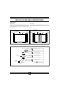
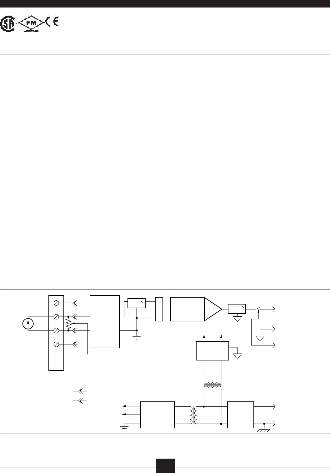
FIGURE 1. OM5-II Block Diagram.
LPF
+In
–In
–EXC
Backpanel
Term Block
1
2
NC
6
5
3
NC
Surge
Suppression
and
Protection
Isolated
Field-Side
Power
4
3
2
1
+EXC
–V
+V
I
IN
4
NC
20
Ω
0.1% plug-in
–V
LPF
+V
Power
Oscillator
Isolated
Computer-Side
Power
V
OUT
20
22
I/O Common
RD EN\
+5V
17
16
Power Common
NC
19
Isochopper™
Amplifier
Pat Pending