


48
OM5-BP-SKT-C ANALOG MODULE EVALUATION BOARD
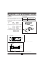
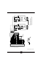
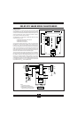
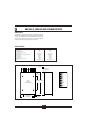
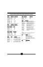
FIGURE 19. OM5-BP-SKT-C Evaluation Board Dimensions And Pin Layout.
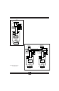
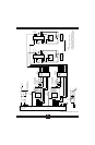
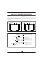
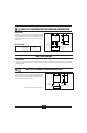
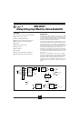
FIGURE 20. OM5-BP-SKT-C Evaluation Board Schematic.
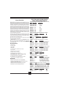
DESCRIPTION
The OM5-BP-SKT-C is a single channel board with a test socket for OM5
module evaluation (Figure 19). All signal input/output, control, and power
connections are connected to terminal blocks for ease of user access. A cold
junction temperature sensor circuit is included for evaluation of thermo-
couple modules. (See Figure 20 for schematic).
The OM5-BP-SKT-C is mechanically compatible with DIN rail mounting
using the following elements:
2 OM7-DIN-SF base elements with snap foot
2 OM7-DIN-SE side elements
4 OM7-DIN-CP connection pins
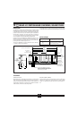
Two jumpers are provided for customer use. The first, J1, provides a current
path between +5V Power Common (module pin 16) and I/O Common
(module pin 19). A path must exist between the host control logic power
common and module I/O Common for proper operation of the module output
switch or track-and-hold circuit. If this connection exists elsewhere in the
system, jumper J1 should be removed since possible ground loops could
exist. Other connections of power ground and signal ground usually occur
at the A/D or D/A converter of the host measurement system.
Jumper J2 is used in the cold junction compensation circuit. If it is installed,
the compensation circuit is enabled and will provide the proper compensa-
tion voltage to correct for the thermoelectric effect at the +In and –In screw
terminals. If an external simulation voltage is desired for cold junction
compensation, J2 should be removed. The external voltage is applied at the
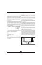
sockets labled CJC+ and CJC–. An external voltage of 510.0 mV corresponds
to an ambient temperature of +25 °C. The transfer function of the onboard
compensation circuit is V
CJC
= 0.510 –0.0025(T–25)V.
Control Local I/O
0.25" (6.4mm) Typical
2.85"
(72.4mm)
0.25"
(6.4mm)
Typical
RD EN\
WR EN\
Reserved
PCOM
V
OUT
I/O COM
V
IN
I/O COM
TB3
+5V
PCOM
J1
J2
–
+
CJC
–EXC
–In
+EXC
+In
4.25"
(108mm)
TB4
TB1 TB2
OMX-1362-C
OMX-CJC-C
22
20
18
16
6 +In
4 +EXC
2 +SEN
–In 5
–EXC 3
–SEN 1
23
21
19
17
PCOM
I/O COM
–EXC +EXC–In +In
V
OUT
I/O COM
V
IN
I/O COM
RD EN\
WR EN\
Reserved
PCOM
TB1
PCOM
TB3
+5
PCOM
PCOM
TB4
I/O COM
PCOM
J1
CJC
+
–
TB2
NOTES:
1. J1 and J2 are factory installed.
2. SCMXCJC is a CJC temperature sensor.
3. Resistor SCMXR1 is an optional I/V conversion
resistor for current inputs, not factory installed.
DZ1
LED
OMX-1362-C
OM5
J2
OMX-CJC-C