


28
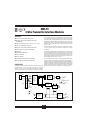
OM5-IFI
Frequency Input Modules
FEATURES
● ACCEPTS FREQUENCY INPUTS OF 0 to 100kHz
● PROVIDES HIGH LEVEL VOLTAGE OUTPUTS
● TTL LEVEL INPUTS
● 1500 VOLT TRANSFORMER ISOLATION
● ANSI/IEEE C37.90.1-1989 TRANSIENT PROTECTION
● INPUT PROTECTED TO 240VAC CONTINUOUS
● ±0.05% ACCURACY
● MIX AND MATCH OM5 TYPES ON BACKPANEL
● CSA CERTIFIED, FM APPROVED, CE COMPLIANT
DESCRIPTION
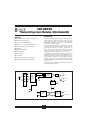
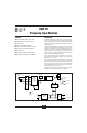
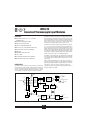
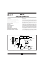
Each OM5-IFI Frequency input module provides a single channel of fre-
quency input which is isolated and converted to a high level analog voltage
output. This voltage output is logic switch controlled, which allows these
modules to share a common analog bus without the requirement of external
multiplexers (Figure 1).
The frequency input signal can be a TTL level signal or a zero-crossing signal.
Terminal 3 (+In) on the field-side terminal block is the “common” or ground
connection for input signals. A TTL signal is connected from terminal 2 (–In)
to terminal 3 (+In), while a zero-crossing signal is connected from terminal 4
(+EXC) to terminal 3 (+In). Input circuitry for each of the signal types has
hysteresis built in. An input signal must cross entirely through the hysteresis
region in order to trigger the threshold comparator.
A 5.1V excitation is available for use with magnetic pick-up or contact-
closure type sensors. The excitation is available on pin 1 (–EXC) and the
excitation common is pin 3 (+In).
The modules are designed with a completely isolated computer side circuit
which can be floated to ±50V from Power Common, pin 16. This complete
isolation means that no connection is required between I/O Common and
Power Common for proper operation of the output switch. If desired, the
output switch can be turned on continuously by simply connecting pin 22,
the Read-Enable pin to I/O Common, pin 19.
A special circuit in the input stage of the module provides protection against
accidental connection of power-line voltages up to 240VAC.
FIGURE 1. OM5-IFI Block Diagram.
Threshold
Comparator
+In
–In
–
+
+
–
–EXC
Backpanel
Term Block
1
2
NC
6
5
3
5.1V
Surge
Suppression
and
Protection
Isolated
Field-Side
Power
4
3
2
1
+EXC
–V
+V
TTL
Inputs
4
–V
LPF
+V
Power
Oscillator
Isolated
Computer-Side
Power
V
OUT
20
22
I/O Common
RD EN\
+5V
17
16
Power Common
NC
19
Signal
Isolation
Zero-Crossing
Inputs
F to V