


37
ELECTRICAL
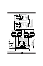
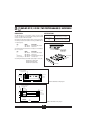
P1 AND P2 CONNECTOR
Connection to the host system is made at connectors P1 and P2. These
connectors are electrically equivalent. Two connectors are provided to allow
both analog input and analog output from host systems having individual
input and output connectors.
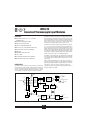
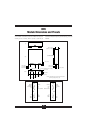
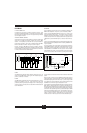
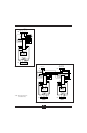
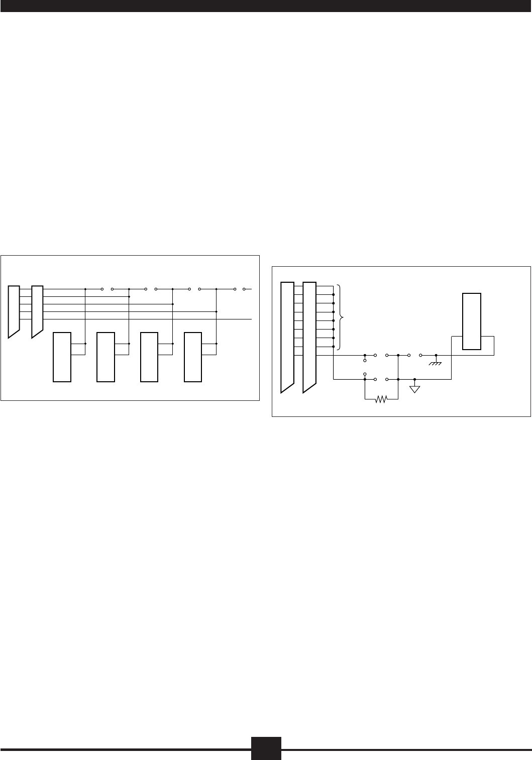
ADJACENT CHANNEL JUMPERS
Adjacent channels may be connected together to provide an isolated output
signal from an isolated input module, providing two levels of 1500V
isolation. This capability is provided with the 15 jumpers labeled JP1
through JP15 on headers E1, E2, and E3. A simplified drawing of the OM5-
BP-16-C schematic for Channel 1 through 4 is shown in Figure 3.
Example: Assume an OM5-IMV input module is installed in Channel 1
position and an OM5-IVI output module is installed in Channel 2 position.
If JP1 is installed, the output of Channel 1 is connected to the input of Channel
2, which provides two levels of 1500V isolation.
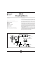
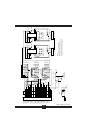
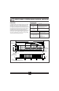
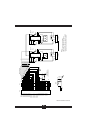
GROUNDING
Figure 4 details the optional ground jumper configuration available on the
OM5-BP-16-C backpanel. Jumpers J1, J3, and J4 are factory installed.
Jumper J1 connects the AGND shield wires (pins 3, 6, 9, 12, 15, 18, 21, and
24) to the backpanel signal ground. This provides a ground connection
between the host system and backpanel. Jumper J1 is required if output
modules are used, or if there is no high impedance sense input (input low of
a differential or pseudo-differential system) on the host measurement sys-
tem.
Jumper J3 connects the SENSE line (pin 25) to the backpanel signal ground.
If the host system has the capability, this allows measuring the OM5-BP-16-
C ground potential.
For proper operation of the output switch or track-and-hold circuit when
using the OM5 backpanels, a current path must exist between the host control
logic power common and module I/O Common (module pin 19). This path
can be established on the OM5-BP-16-C via jumper J4. If this connection
exists elsewhere in the system, jumper J4 should be removed since possible
ground loops could exist. Other connections of power ground and signal
FIGURE 3. OM5-BP-16-C Adjacent Channel Jumpers.
ground usually occur at the A/D or D/A converter of the host measurement
system.
If the connection of power common and AGND shield wires exists in the host
measurement system, an optional resistive connection between AGND and
the backpanel signal ground can be made via R
1
. R
1
can be as large as 10K
ohms; 100 ohms is a recommended value. Jumper J2 can be used to connect
the SENSE line to R
1
when this ground configuration is used.
For full protection against large electrical disturbances on the field-side of the
OM5 modules, a #10-32 ground stud is provided on the backpanel. An
electrical connection between this ground stud and system ground should be
provided with a large gauge wire of the shortest possible length. When this
connection is made, a possible ground loop could result through the AGND
shield wires and backpanel signal ground. If the application involves only
input modules and a differential input is used by the host measurement
system, J1 should be removed. Remember that J1 is required if output
modules are used or if the host system does not have differential inputs.
FIGURE 4. OM5-BP-16-C Grounding Diagram.
POWER
The OM5-BP-16-C backpanel requires external +5VDC ±5% power. The
chassis mounted OMX-976-C power supplies have adequate capacity to
power any combination of modules.
FUSING
The OM5-BP-16-C backpanel power is fuse protected through F1. This is a
Littlefuse type 252004, 4 amp fuse. Zener diode DZ1 provides extra
protection by clamping the input power voltage to +5.6V. If the input supply
voltage connection is reversed, this zener diode will be forward biased and
fuse F1 will be blown.
P1
1
5
7
11
13
P2
V
OUT
20
V
IN
18
CH 1
V
OUT
20
V
IN
18
CH 2
20
18
CH 3
20
18
CH 4
12 34 56
JP4
HD10, E1
JP1 JP2 JP3
V
OUT
V
IN
V
OUT
V
IN
SCM5B
P1
3
6
9
12
15
P2
J3
19
OM5 Module
18
21
24
25
J1
J2
Sense
AGND
Signal Ground
and
Grounding Bolt
R
1
J4
Power Common
16I/O COM PWR COM