


40
ELECTRICAL
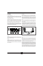
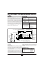
P1 CONNECTOR
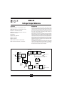
The 26 pin P1 connector provides the signal interface between the OM5-BP-
16-MUX-C backpanel and the host measurement system. Two separate
analog bus connections are provided; one for analog input signals and one
for analog output signals. Two sets of six address lines and an enable pin
allow input and output modules to be independently multiplexed onto their
respective analog signal bus. R0 thru R5 and RDENAB are used for input
modules, and W0 thru W5 and WRENAB are used for output modules.
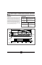
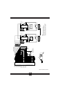
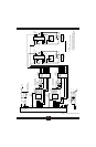
ADDRESS SELECTION
The OM5-BP-16-MUX-C backpanel has address decoding circuitry to allow
multiplexing any combination of up to 16 input or output modules. Capability
is also provided in the address decode circuitry to expand the system to 64
channels (four OM5-BP-16-MUX-C backpanels) of multiplexed input or
output. Jumpers on HD10 header, E1 and E2 group, select which set of 16
addresses are assigned to a particular backpanel. The E1 group assigns a set
of 16 addresses for input modules, and the E2 group assigns a set of 16
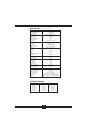
addresses for output modules. The table below shows the correlation of
jumper position to address range.
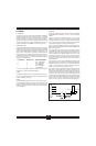
E1 Jumper Pos E2 Jumper Pos Address Range/Mode
4 4 0-15, STAND ALONE
3 3 48-63, EXPANDED
2 2 32-47, EXPANDED
1 1 16-31, EXPANDED
0 0 0-15, EXPANDED
To connect multiple OM5-BP-16-MUX-C backpanels in this expanded
configuration, use interconnect cable OM5-CAB-01-C.
POWER
The OM5-BP-16-MUX-C backpanel requires external +5VDC ±5% power.
The chassis mounted OMX-976 power supplies have adequate capacity to
power any combination of modules.
FUSING
The OM5-BP-16-MUX-C backpanel power is fuse protected through F1.
This is a Littlefuse type 252004, 4 amp fuse. Zener diode DZ1 provides extra
protection by clamping the input power voltage to +5.6V. If the input supply
voltage connection is reversed, this zener diode will be forward biased and
fuse F1 will be blown.
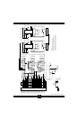
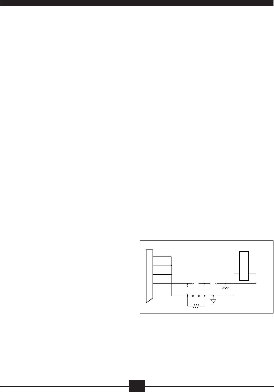
GROUNDING
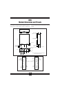
Figure 7 below details the optional ground jumper configuration available on
the OM5-BP-16-MUX-C backpanel. Jumpers J1, J2, and J4 are factory
installed.
Jumper J1 connects the SIG COM shield wires (pins 2, 5, and 6) to the
backpanel signal ground. This provides a ground connection between the
host system and backpanel. Jumper J1 is required if output modules are
used, or if there is no high impedance sense input (input low of a differential
or pseudo-differential system) on the host measurement system.
Jumper J2 connects the SNS LO line (pin 4) to the backpanel signal ground.
If the host system has the capability, this allows measuring the OM5-BP-16-
MUX-C ground potential.
For proper operation of the output switch or track-and-hold circuit when
using the OM5-BP-16 backpanels, a current path must exist between the host
control logic power common and module I/O Common (module pin 19). This
path can be established on the OM5-BP-16-MUX-C via jumper J4. If this
connection exists elsewhere in the system, jumper J4 should be removed
since possible ground loops could exist. Other connections of power ground
and signal ground usually occur at the A/D or D/A converter of the host
measurement system.
If the connection of power common and SIG COM shield wires exist in the
host measurement system, a resistive connection between SIG COM and the
backpanel signal ground can be made via R
1
. R
1
can be as large as 10K ohms;
100 ohms is a recommended value. Jumper J3 can be used to connect the
SNS LO line to R
1
when this ground configuration is used.
For full protection against large electrical disturbances on the field-side of the
OM5 modules, a #10-32 ground stud is provided on the backpanel. An
electrical connection between this ground stud and system ground should be
provided with a large gauge wire of the shortest possible length. When this
connection is made, a possible ground loop could result through the SIG
COM shield wires and backpanel signal ground. If the application involves
only input modules and a differential input is used by the host measurement
system, J1 should be removed. Remember that J1 is required if output
modules are used or if the host system does not have differential inputs.
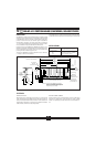
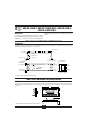
FIGURE 7. OM5-BP-16-MUX-C Grounding Diagram.
P1
2 SIG COM
5 SIG COM
J2
19
OM5 Module
6 SIG COM
4 SIG COM
J1
J3
Signal Ground
and
Grounding Bolt
R
1
J4
Power Common
16I/O COM PWR COM