


28
W415-0661 / C / 02.20.08
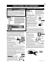
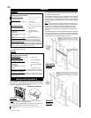
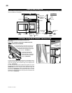
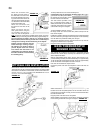
NOTE: THE OPTIONAL CLEAN FACE TRIM KIT MUST BE
INSTALLED BEFORE PROCEEDING.
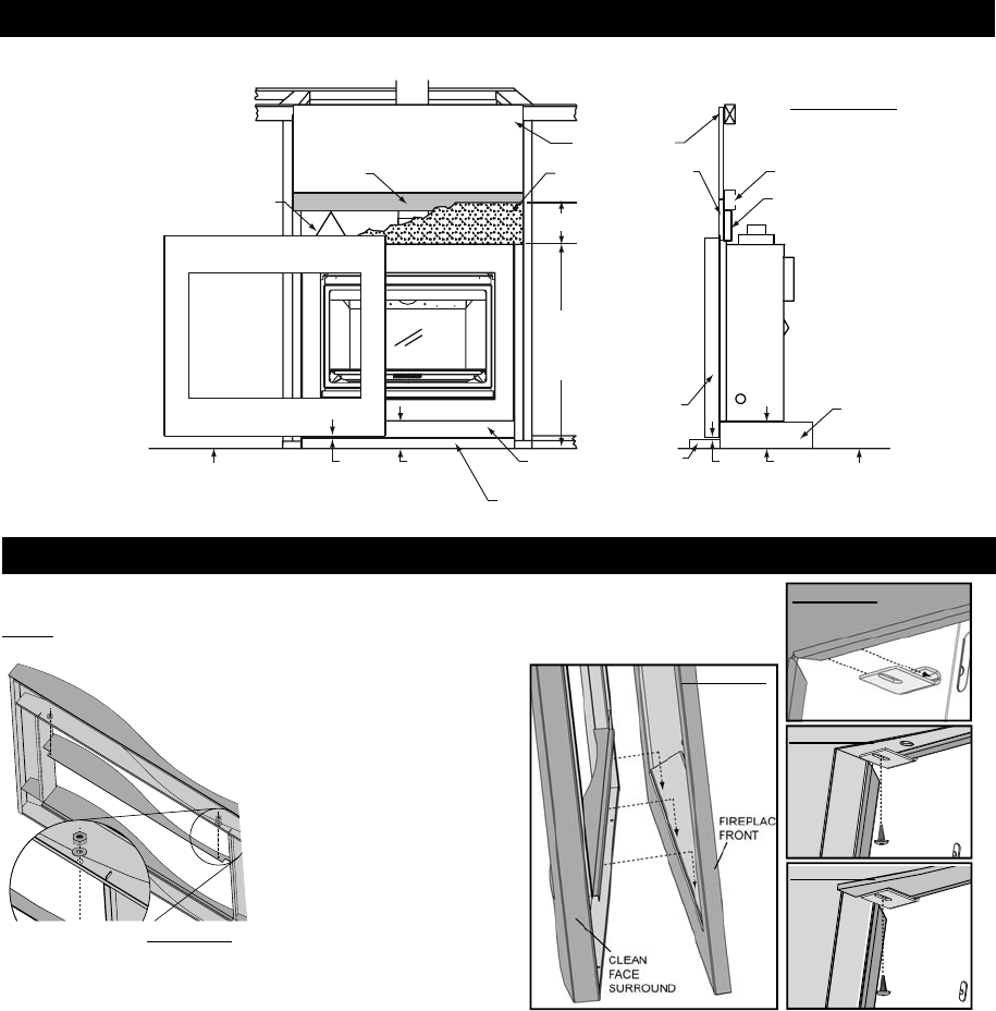
1. From the rear side of the clean face surround,
insert the weld studs on the top window plate
assembly upward through the holes on the
underside of the top section of the clean
face surround. (FIGURE 87)
2. Using a socket wrench,
secure using the nuts and
washers provided. Depending
on your surround, space may
be tight. (FIGURE 87)
FIGURE 87
FIGURE 88
FIGURE 89
FIGURE 90
FIGURE 91
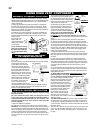
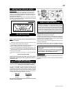
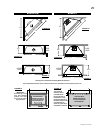
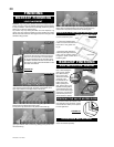
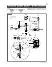
3. First secure the clean face surround to the fi replace front by
hooking the ledge that runs horizontally on the rear surface of the
clean face surround over the bottom edge of the fi replace front
opening. (FIGURE 89)
4. With the clean face surround against the fi replace front, hook
the surround clips in behind the top lip of the fi replace front opening
(FIGURE 89) and secure using the screws provided through the
slot in the surround clip and into the pre-drilled hole in the clean
face surround. (FIGURE 89) If the optional clean face trim kit was
installed, the surround clip fi ts into the cut out and is secured in the
same fashion. (FIGURE 90)
The “wave” clean face surround kit is shown in all
illustrations.
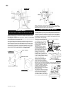
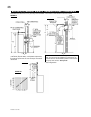
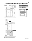
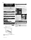
HEARTH INSTALLATION
FINISHED
FLOOR
3
/8”
CLEARANCE
CLEANFACE SURROUND
STAND-OFF
6
1
/2” MINIMUM
FINISHED
FLOOR
NON-COMBUSTIBLE
MATERIAL
COMBUSTIBLE
MATERIAL
FIREPLACE
RISER
3
/8”
CLEARANCE
3
3
/8”
PLUS
HEARTH
HEIGHT
FIREPLACE
RISER
STAND-OFF
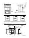
CLEAN FACE SURROUND KIT
CLEAN FACE
SURROUND
KIT
HEARTH
HEARTH
3
3
/8”
PLUS
HEARTH
HEIGHT
37
3
/8”
PLUS
HEARTH
HEIGHT
STEEL
HEADER
STEEL
HEADER
When installing to a hearth the fi replace riser must create a minimum clearance of 3 3/8" PLUS the height of the hearth from the fi nished
fl oor to the bottom of the fi replace.
FIGURE 86b
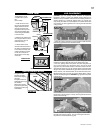
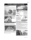
OPTIONAL CLEAN FACE TRIM KIT INSTALLATION