


24
W415-0661 / C / 02.20.08
FRAMING
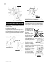
BGD42CF
BGD36CF(G)
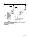
FIGURE 67
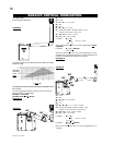
FIGURE 68
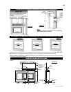
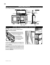
It is not necessary to install a hearth extension with this fi replace sys-
tem. Objects placed in front of the fi replace should be kept a minimum
of 48" away from the front face.
When roughing in the fi replace, raise the fi replace to accommodate
for the thickness of the fi nished fl oor materials, i.e. tile, carpeting,
hard wood, which if not planned for will interfere with the opening of
the lower access door and the installation of many decorative fl ashing
accessories.
Note: In order to avoid the possibility of exposed insulation or vapor
barrier coming in contact with the fi replace body, it is recommended
that the walls of the fi replace enclosure be “fi nished” (ie: drywall/
sheetrock), as you would fi nish any other outside wall of a home.
This will ensure that clearance to combustibles is maintained within
the cavity.
Combustible materials may be installed fl ush with the front of the fi re-
place but must not cover any of the black face-areas of the fi replace.
Non-combustible material (brick, stone or ceramic tile) may protrude
in these areas but must not restrict glass door removal.
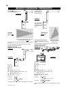
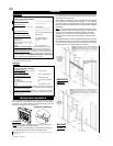
INSTALLING STANDOFFS
Both the BGD36CF(G) and BGD42CF are supplied with two standoffs.
For convenience, the standoffs have been shipped fl at and located on
the top at the front. Before framing ensure the standoffs are bent up and
screwed into place ensuring a height of 4.5".
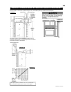
BGD36 ILLUSTRATION
FIGURE 66
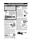
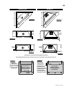
HORIZONTAL VENT SECTIONS: - A minimum clearance of 1" at the
bottom and sides of the vent and 2" at the top on all horizontal runs to
combustibles is required. Use fi restop spacer W010-1774 (supplied).
VERTICAL VENT SECTIONS: - A minimum of 1" all around the vent pipe
on all vertical runs to combustibles is required except for clearances in
fi replace enclosures
*. See "MINIMUM ENCLOSURE CLEARANCES"
section. Use fi restop spacer W500-0096 (not supplied).
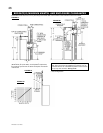
MINIMUM CLEARANCE TO COMBUSTIBLE CONSTRUCTION FROM
FIREPLACE AND VENT SURFACES:
Non-Combustible framing:
Top 0" to stand-offs if using optional
clean face surround
Combustible framing:
Sides, back, and bottom of the unit 0" to stand-offs
Top 3 1/2" to stand-offs if using
optional clean face surround
Non-combustible fi nishing:
Top 6 1/2" if using optional clean
face surround
Combustible fi replace fi nishing:
Sides, bottom and top 0" to fi replace edge
Enclosure top 8 1/4" to top of fi replace
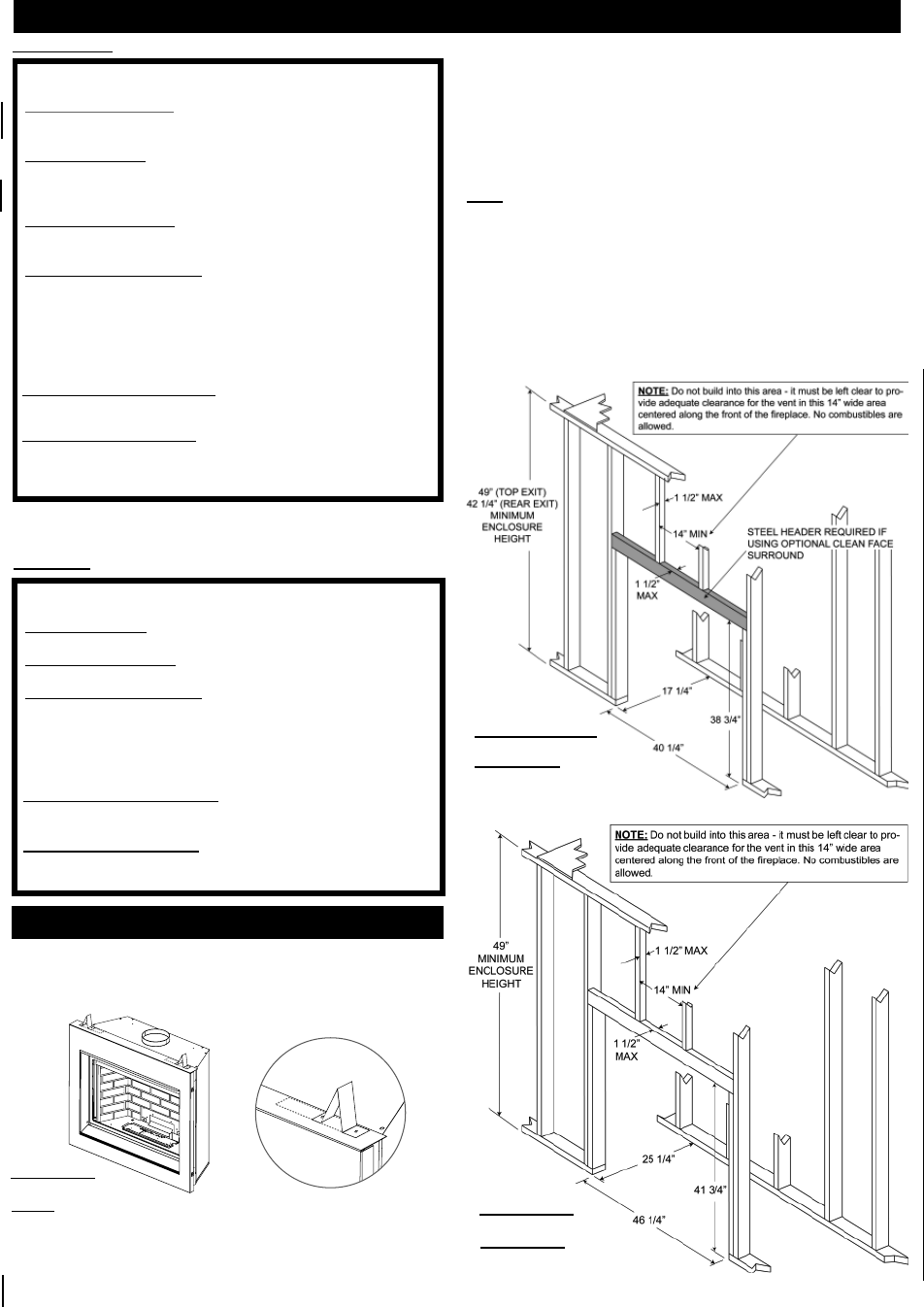
Recessed depth 17 1/4"
Sides and bottom of the vent pipe 1"
Top of vent pipe 2"
Ceiling 72" from bottom of unit
MINIMUM CLEARANCE TO COMBUSTIBLE CONSTRUCTION FROM
FIREPLACE AND VENT SURFACES:
Combustible framing:
Top, sides, back and bottom of the unit 0" to stand-offs
Non-combustible fi nishing:
Top 6 1/2" to fi replace edge
Combustible fi replace fi nishing:
Sides and bottom 0" to fi replace edge
Enclosure top 13 1/2" to top of fi replace
Recessed depth 25"
Top, sides and bottom of vent pipe
2"
Ceiling 72" from bottom of unit
BGD42CF
HORIZONTAL VENT SECTIONS: A minimum clearance of 2" all around
the vent pipe on all horizontal runs to combustibles is required. Use fi restop
spacer W010-1778 (supplied).
VERTICAL VENT SECTIONS: A minimum of 1" all around the vent pipe
on all vertical runs to combustibles is required. Use fi restop spacer W500-
0028 (not supplied).
BGD36CF(G)
NOTE: The information and dimensions in this section represent the
minimum clearances to combustible material.
It is best to frame your fi replace after it is positioned and the vent sys-
tem is installed. Use 2x4's and frame to local building codes.
BGD36CF(G) ONLY: A steel header is required if using optional clean
face surround.
* Vertical vent sections in fi replace enclosures require a minimum of
1 1/2" all around the vent pipe.