


6
WI1370 XP-400 Installation Instructions
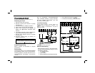
Installation
Mounting the Panel
Mount the Panel close to an unswitched AC
source, a cold-water pipe ground, and a
telephone line connection.
Mounting the Keypad
A keypad should be located near an exit/entry
door. To remove the keypad from the backplate,
insert a small screwdriver into the slots at the
bottom of the keypad. Pull up on the
screwdriver to pop off the cover.
Up to 3 keypads can be connected on individual
wire runs with #22 AWG wire with a maximum
total cable length of 1000 feet. Each keypad
draws approximately 35 mA.
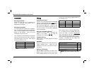
Wiring
Grounding the Panel
Connect the control-panel EARTH GROUND
screw to a metal cold-water pipe. Do
not use a
gas pipe, plastic pipe or AC ground connections.
Use at least #16 AWG wire. Connect a wire
with a ground lug crimped or soldered onto one
end and connect it to the EARTH GROUND
screw in the cabinet.
AC Power and Battery Wiring
Complete all wiring before connecting the
battery or AC Power. Do
not plug the
transformer into a switched outlet.
Telephone Wiring
Wire as shown in the wiring diagram in the back
of this manual.
WARNING
The FCC restricts the use of this equipment on
certain telephone lines. Read the FCC
statement on the back of this manual to ensure
compliance.
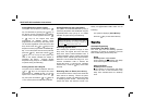
Burglary Zone Wiring
NAPCO’s EZ Zone Doubling
TM
is simple. Each
terminal has 2 zones, use an E (2.2 K) type
Zone Doubling Resistor for the primary zone
and a
Z
(3.9 K) type Zone Doubling Resistor for
the secondary zone.
Wire zones as shown in the wiring diagram (pg.
27). All resistors must be installed, even if the
zone is not used. If required, unsupervised
open circuit devices may be used instead of
closed circuit devices. Program the zone as an
Open Circuit Zone [06] (Zone Doubling Resistor
required). If necessary, use the voltage chart
below to verify proper voltages.
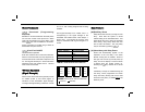
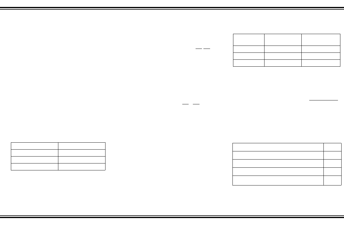
Keypad Wire Color Control Panel Terminal
RED 12 (+PWR)
BLACK 13 (GND)
GREEN 14 (GREEN)
TABLE
1 K
EYPAD
W
IRING
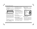
Terminals 2.2 K Primary 3.9 K
3&4 Zone 1 Zone 4
5&4 Zone 2 Zone 5
6&7 Zone 3 Zone 6
TABLE
2
EZ Z
ONE
D
OUBLING
TM
Primary (2.2K) and Secondary (3.9K) zones normal 1.9 V
Secondary (3.9K) open 2.5 V
Primary (2.2K) open 3.2 V
Primary (2.2K) and Secondary (3.9K) open 5.0 V
Primary (2.2K) and/or Secondary (3.9K) shorted
(Sys. Trbl 7-Zone Trbl)
0.0 V
TABLE
3 V
OLTAGE
AT
T
ERMINALS
3&4, 5&4,
6&7