5
Programming the Panel
Refer to XP-400 Programming Instructions (WI1371)
Defaulting the Panel
1. Remove power from the panel.
2. Remove all wiring from terminal 15 (PGM)
and terminal 3.
3. Connect terminal 15 (PGM) to terminal 3.
4. Apply power to the XP-400 control panel.
5. After a few seconds the
W
ARMED,
X
READY and
H
SYSTEM TROUBLE LEDs
will flash.
6. The keypad will beep 3 times indicating the
panel default values have been loaded.
7. Remove wiring between terminal 15 (PGM)
and terminal 3.
8. Re-install original wiring for terminal 15
(PGM) and terminal 3.
Keypad Programming
Refer to WI1371 for information on keypad
programming.
Downloading
The XP-400 panel can be download/uploaded
with PCD3000 software using the Ring Method,
Answering Machine Override (Second Call) or
A6
Method of downloading. The panel can
also be automatically downloaded/uploaded
using PCD2000 Software running PCPreset.
For Site Initiated Downloaded, see Auto
Download ID Number [93].
Local Downloading
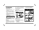
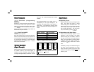
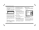
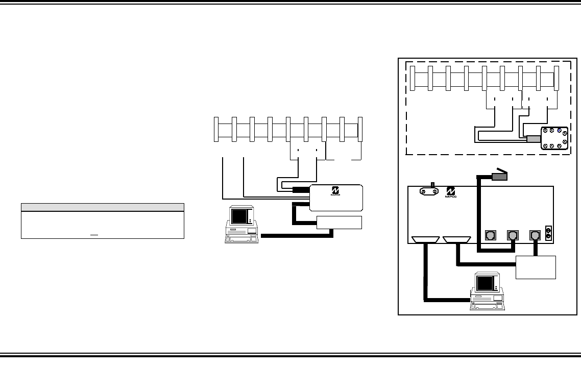
Wire as shown in Figure 1. Use the power up or
A6
method of establishing a connection. The
power up method is recommended if the panel is
attempting to report.
Remote Downloading
Wire as shown in Figure 2. The panel can be
remotely download/uploaded using any one of
the following methods:
1. The
A6
method
2. Call-in method
3. Answering Machine Override (Second Call)
4. Site-Initiated (PCPreset &
A6
)
5. Automatic Downloading (Using PCPreset)
MODEM
J1
TO COMPUTER
J3
LOCAL
TO
PCI2000
J2
TO EXTERNAL
MODEM
J4
TELCO
J5 LINE
OUT TO
TELCO
FIGURE
2 R
EMOTE
D
OWNLOAD
PGM
(-)
+12
-13 14 15
16 17 18 19
+PWR GND GREEN
PHONE TELCO
GREEN
RED
XP-400 Panel at the site
RING TIP RING
RJ31X
TIP
GRY
BRN
PGM
(-)
+12
-13 14 15
16 17 18 19
+PWR GND GREEN TIP RING
PHONE
PCL2000A
GREEN
RED
MODEM
FIGURE
1 L
OCAL
D
OWNLOAD
TIP RING
TELCO
BLACK RED
N
OTE
:
Any programming in Dealer Options 1 [96] and Dealer Options
2 [97] will not be defaulted. If Dealer Code Lockout has been
programmed the panel will not default the Dealer Code.


