


1 - 9
1 OVERVIEW
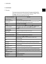
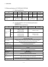
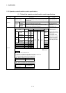
1.2.3 Operation control/transition control specifications
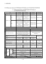
(1) Table of the operation control/transition control specifications
Item Specifications Remark
Calculation expression
Returns a numeric result.
Expressions for calculating indirectly specified data using constants
and word devices.
D100+1,SIN(D100), etc.
Bit conditional
expression
Returns a true or false result.
Expression for judging ON or OFF of bit device.
M0, !M0, M1*M0,
(M1+M2)*(!M3+M4), etc.
Expression
Conditional
expression
Comparison
conditional
expression
Expressions for comparing indirectly specified data and calculation
expressions using constants and word devices.
D100==100
D10<D102+D10, etc.
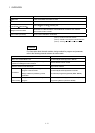
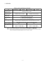
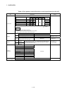
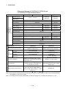
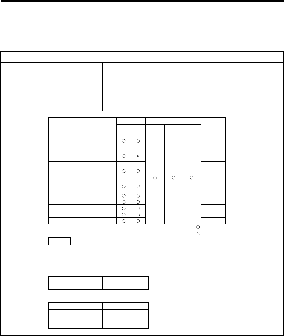
Accessibility Usable tasks
Device Symbol
Read Write Normal Event NMI
Description
example
The input X/output Y are
written with the actual input
PX/actual output PY.
Input module
non-loaded
range
X
X100
Input
Input module
loaded range
PX
PX180
Output module
non-loaded
range
Y
Y100
Output
Output module
loaded range
PY
PY1E0
Internal relay M
M20
Latch relay L
L1000
Link relay B
B3FF
Annunciator F
F0
Special relay M
M9000
: usable
: unusable
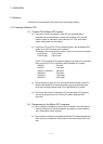
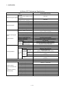
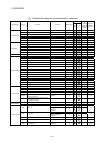
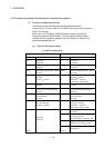
CAUTION
<Restrictions on write-enabled bit devices>
1) Write to device X is allowed only within the input module non-installed range.
2) Special relay has predetermined applications in the system.
Do not perform write to other than the user setting device.
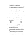
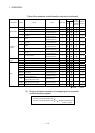
(Note) : SET/RST is disabled in the following device ranges.
SET/RST disable range Remark
M2001 to M2032 Start accept device
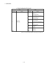
(Note) : DOUT output disabled in the following device ranges.
DOUT output disable range Remark
Designation including
M2000 to M2127
Dedicated device
M9000 to M9255 Special relay
Bit devices
It does the layput of the I/O
numbers of PX, PY by a set
up of as system.
(In the operation control
program/transition program,
automatically represented
as PX/PY according to the
system setting information.)