


1 - 88
1 OVERVIEW
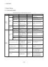
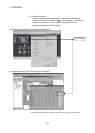
(b) Operation setting upon STOP
RUN
Set the condition in which the "PLC ready" flag (M2000) turns ON. Select
one of the following:
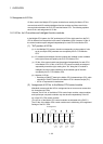
1) M2000 ON upon switching (STOP
RUN) (default)
Condition in which the M2000 turns from OFF to ON
• Change the RUN/STOP switch from the STOP side to the RUN side.
• With the RUN/STOP switch set to the RUN side, turn ON the power
or cancel the reset.
Condition in which the M2000 turns from ON to OFF
• Change the RUN/STOP switch from the RUN side to the STOP side.
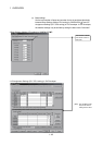
2) M2000 ON upon switching (STOP
RUN) + 1 set in setting register
(The M2000 turns ON when the switch is set to the RUN side and 1 is
set in the setting register.)
Condition in which the M2000 turns from OFF to ON
• With the RUN/STOP switch set to the RUN side, set 1 in the setting
register for "PLC ready" flag (D704). (The Motion CPU detects a
change from 0 to 1 in the lowest bit in the D704).
Condition in which the M2000 turns from ON to OFF
• With the RUN/STOP switch set to the RUN side, set 0 in the setting
register for "PLC ready" flag (D704). (The Motion CPU detects a
change from 1 to 0 in the lowest bit in the D704).
• Change the RUN/STOP switch from the RUN side to the STOP side.
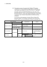
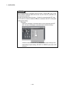
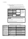
(c) Forced stop input setting
Specify the bit device used for executing a forced stop in which all servo-
amplifier axes are stopped immediately.
Either X (PX) or M can be specified. No default value has been set. The set
bit device is designated as contact B and performs the following control in
response to ON/OFF of the device.
• Bit device is turned OFF --- Forced stop input is ON (forced stop)
• Bit device is turned ON --- Forced stop input is OFF (forced stop is
released.)
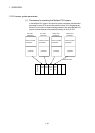
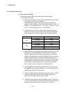
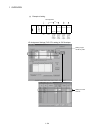
(d) Latching range setting
Set the following latching ranges for M, B, F, D and W, respectively.
• Range in which the latch can be cleared with the latch clear key (Latch (1))
• Range in which the latch cannot be cleared with the latch clear key (Latch
(2))