


3 - 15
3 COMMUNICATION BETWEEN THE PLC CPU AND THE MOTION CPU IN
THE MULTIPLE CPU SYSTEM
•
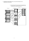
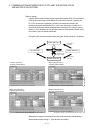
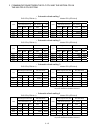
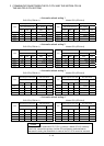
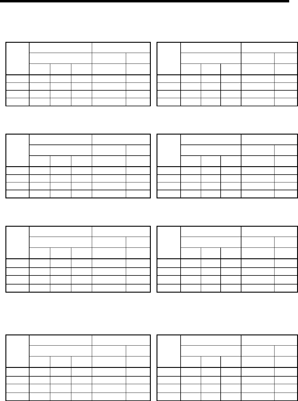
Automatic refresh setting 1
PLC CPU (CPU No.1) Motion CPU (CPU No.2)
Send range for each CPU CPU side device Send range for each CPU CPU side device
CPU share memory G Dev. starting M0 CPU share memory G Dev. starting *
CPU
Point Start End Start End
CPU
Point Start End Start End
No.1 48 M0 M767 No.1 48 M3072 M3839
No.2 66 M768 M1823 No.2 66 M2000 M3055
No.3 0 No.3 0
No.4
No.4
•
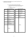
Automatic refresh setting 2
PLC CPU (CPU No.1) Motion CPU (CPU No.2)
Send range for each CPU CPU side device Send range for each CPU CPU side device
CPU share memory G Dev. Starting D0 CPU share memory G Dev. starting *
CPU
Point Start End Start End
CPU
Point Start End Start End
No.1 118 D0 D117 No.1 118 D640 D757
No.2 640 D118 D757 No.2 640 D0 D639
No.3 0 No.3 0
No.4
No.4
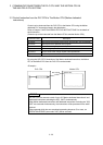
•
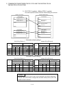
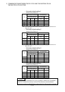
Automatic refresh setting 3
PLC CPU (CPU No.1) Motion CPU (CPU No.2)
Send range for each CPU CPU side device Send range for each CPU CPU side device
CPU share memory G Dev. Starting M1824 CPU share memory G Dev. starting *
CPU
Point Start End Start End
CPU
Point Start End Start End
No.1 48 M1824 M2591 No.1 48
* *
No.2 0 No.2 0
No.3 66 M2592 M3647 No.3 66
* *
No.4
No.4
(Note) : A dummy setting is made so that an excessive device
may not be refreshed in the Motion CPU No.2.
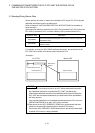
•
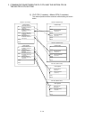
Automatic refresh setting 4
PLC CPU (CPU No.1) Motion CPU (CPU No.2)
Send range for each CPU CPU side device Send range for each CPU CPU side device
CPU share memory G Dev. starting D758 CPU share memory G Dev. starting *
CPU
Point Start End Start End
CPU
Point Start End Start End
No.1 118 D758 D875 No.1 118
* *
No.2 0 No.2 0
No.3 640 D876 D1515 No.3 640
* *
No.4
No.4
(Note) : A dummy setting is made so that an excessive device
may not be refreshed in the Motion CPU No.2.