


4 - 3
4 STRUCTURE OF THE MOTION CPU PROGRAM
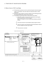
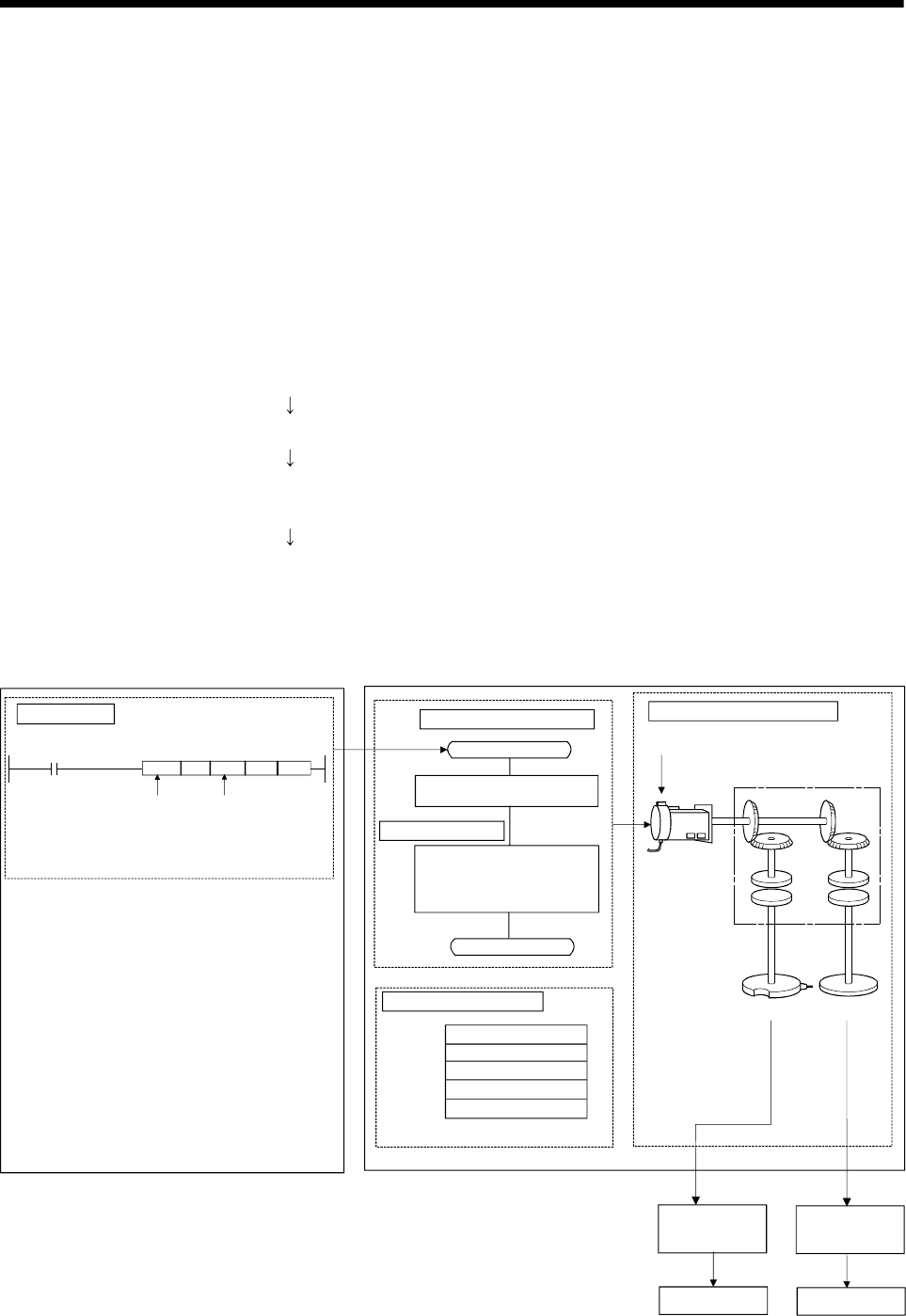
4.2 Motion Control in SV22 Virtual Mode
(1) Software-based synchronous control is performed using the mechanical system
program constructed by virtual main shaft and mechanical module in (SV22)
virtual mode.
(2) Mechanical system programs is required in addition to the positioning parameter,
servo program/Motion SFC program used in real mode.
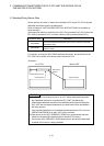
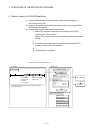
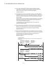
(3) The procedure of positioning control in virtual model is shown below:
1) Motion SFC program for virtual mode is requested to start using the
S(P).SFCS instruction of the PLC program.
(Motion SFC program can also be started automatically by parameter
setting.)
2) The virtual servomotor in the mechanical system program is started.
3) Output the operation result obtained through the transmission module to
the servo amplifier set as the output module.
4) The servomotor is controlled.
<Motion CPU>
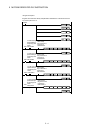
Program structure in SV22 virtual mode
Servo amplifier
Servomotor
Mechanical system program
Drive module
(Virtual servomotor)
Transmission module
(Axis 1)
Output module
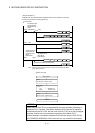
• Home position return data is not used, since home position return cannot be performed in virtual mode.
(Home position return is executed in real mode.)
• JOG operation in virtual mode is controlled using the JOG operation data set by drive module parameters.
Servo amplifier
Servomotor
<PLC CPU>
SP.SFCS
••••
K0
(Note-1) : The Motion SFC program can also be started
automatically by parameter setting.
Start request
instruction of
the Motion
SFC program
Specification of starting
program No.
Motion SFC program
Transfer
[G200]
M2044//on virtual mode?
[K100: virtual]
1 VF
Axis 1,
Combined D 0 PLS/s
END
4)
4)
3)
3)
1)
2)
•••• ••••
Positioning control parameters
System settings
Fixed parameters
Servo parameters
Parameter blocks
Limit switch output data
Servo program
PLC program