


43
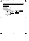
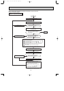
OPERATING PROCEDURE
PHOTOS
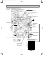
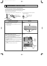
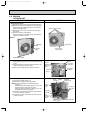
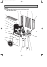
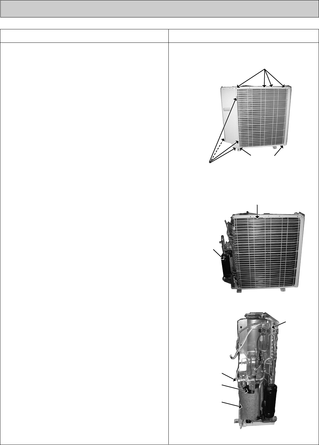
Photo 5
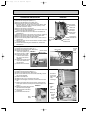
Photo 6
Photo 7
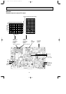
Heat exchanger
Accumulator
Stop valve
Compressor
Soundproof
felt
Screw of the
separator
Screws of the
rear guard
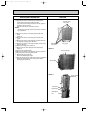
Screws of the
rear guard
Screws of the
rear panel
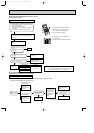
4. Removing the heat exchanger and compressor
(1) Remove the screws of the rear panel. Remove the
screws of the valve bed and the valve bed.
(The valve bed is fixed by the catches on the right and
left sides. Lift it to remove.)
Open the rear panel to the rear to remove.
NOTE :
All panels are fixed by catches, and must be removed
by up and down.
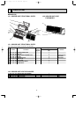
(2) Remove the screws of the side panel and the side
panel.
(Photo 4)
(3) Remove the screws of the rear guard and the rear
guard.
(4) Remove the screws of the separator support plate and
the separator support plate. (Photo 4)
(5) Remove the screws of the motor support and the motor
support. (Photo 4)
(6) Remove the relay panel. (Photo 3)
(7) Remove the fan motor lead wire from lead clamps.
(Photo 4)
(8) Remove the soundproof felt.
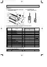
(9) Remove the screws of the separator and the separator.
(10)
Recover gas from the refrigerant circuit.
(11)
Remove the heat exchanger.
Detach the welded part of pipe.
(12)
Remove the nuts of the compressor and the compressor.
Detach the welded part of the suction pipe and the
discharge pipe. (Photo 2)
OB311--2.qxp 04.1.13 10:02 AM Page 43