


40
DISASSEMBLY INSTRUCTIONS
11
11-1. MS24WN
INDOOR UNIT
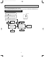
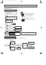
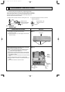
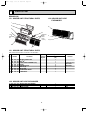
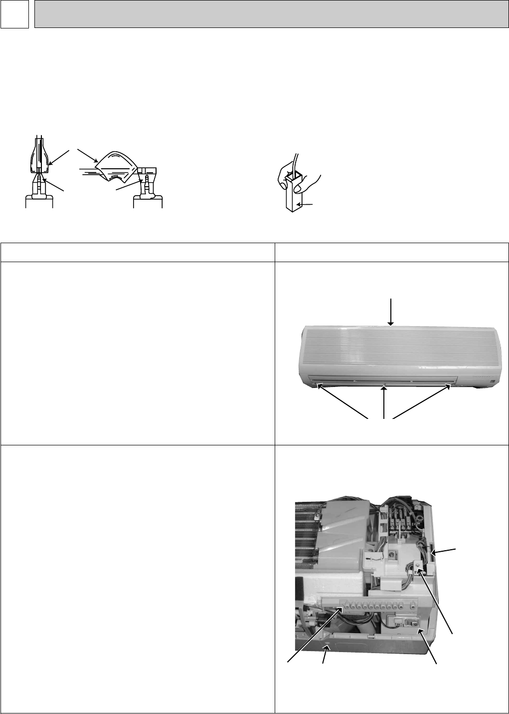
(1) Slide the sleeve and check if there is a locking lever or not. (2) The terminal with this connector is a terminal
with lock mechanism.
1Slide the sleeve.
2Pull the terminal while
pushing the locking
lever.
1Hold the sleeve, and
pull out the terminal
slowly.
In case of terminal with lock mechanism, detach the terminal as shown below.
There are two types ( Refer to (1) and (2)) of the terminal with lock mechanism.
The terminal with no lock mechanism can be removed by pulling it out.
Check the shape of the terminal and work.
<"Terminal with lock mechanism" Detaching points>
Connector
Sleeve
Locking lever
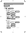
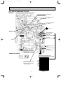
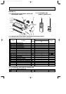
OPERATING PROCEDURE
PHOTOS
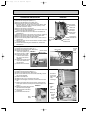
Photo 2
Photo 1
Front panel
Screws
1. Removing the front panel
(1) Remove the screw caps of the front panel.
Remove the screws.
(2) Pull the panel down to your side slightly and unhook the
catches at the top.
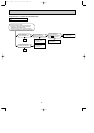
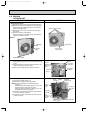
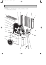
Screw of
the electrical
cover
R.L
holder
Receiver
P.C.
board
2. Removing the electronic control P.C. board, the receiver
P.C. board and the display P.C. board
NOTE : In case of removing only indoor electronic control
P.C. board work (2) and (3) are not necessary.
(1) Remove the front panel. (Refer to 1.)
(2) Remove the R.L holder from the bottom of electrical box.
(3) Open the R.L holder, remove the receiver P.C. board and
the display P.C. board.
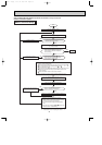
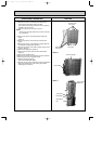
(4) Remove the screw of the electrical cover and the electrical
cover.
(5) Pull out indoor electronic control P.C. board slightly.
(6) Disconnect all the connectors on the electronic control P.C.
board.
(7) Remove the electronic control P.C. board.
Indoor
electronic
control
P.C.board
Screw of
the corner
box
OB311--2.qxp 04.1.13 10:01 AM Page 40