


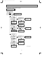
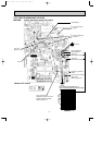
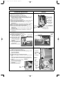
4. Removing the vane motor
(1) Remove the front panel. (Refer to 1.)
(2) Remove the electrical cover. (Refer to 2.)
(3) Remove the lead wire of
vane motor. (Refer to 3.)
(4) Remove the R.L. holder.
(5) Pull out the drain hose
from the nozzle assem-
bly, remove the nozzle
assembly.
(6) Remove the screws of the
vane motor, disconnect
the connector.
(7) Remove the vane motor.
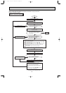
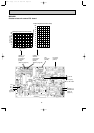
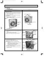
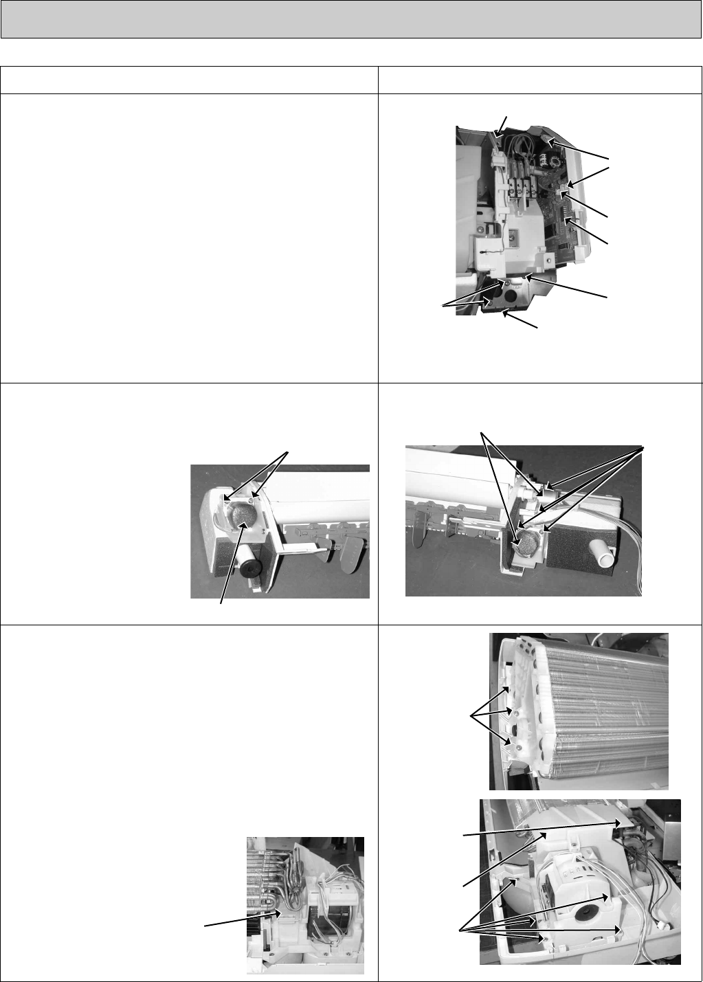
3. Removing the electrical box
(1) Remove the front panel. (Refer to 1.)
(2) Remove the electrical cover. (Refer to 2.)
(3) Disconnect the connector of the indoor coil
thermistor (CN112), the fan motor connector (CN211 and
CN121) and the vane motor connector (CN151) on the
electronic control P.C. board.
(4) Remove the screw of ground wire.
(5) Remove the fan motor lead wire, indoor coil thermistor and
ground wire from the electrical box.
(6) Remove the lead wire of vane motor from the bottom of
electrical box.
(7) Remove the screw of corner box and corner box. (Photo 2)
(8) Remove the screw of conduit cover and conduit cover.
(9) Remove the screws fixing the conduit plate.
(
10
) Pull out the conduit plate and the indoor/ outdoor unit con-
necting wire.
(
11
) Remove the lock nut from the connector of indoor/ outdoor
connecting wire.
(
12
) Remove the screw fixing the electrical box, remove the
electrical box.
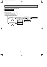
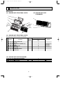
5. Removing the line flow fan and the indoor fan motor
(1) Remove the front panel. (Refer to 1.)
(2) Remove the electrical box. (Refer to 3.)
(3) Pull out the drain hose from the nozzle assembly, remove
the nozzle assembly.
(4) Remove the water cut.
(5) Slide the hole cover, remove the hole cover.
(6) Remove the hexagon socket set screw from the line flow
fan.
(7) Remove the screws fixing the fan motor, remove the fan
motor. (Be careful not to drop the fan motor because it is
heavy.)
(8) Remove the screws fixing the left
side of the heat exchanger.
(9) Lift the left side of the heat
exchanger.
(
10
) Remove the line flow fan.
41
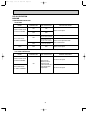
OPERATING PROCEDURE
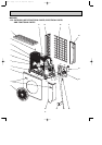
PHOTOS
Photo 4
Photo 6
Vane motors
Indoor
coil
thermistor
Photo 3
Screws fix-
ing the left
side of the
heat
exchanger
Screws
of the
vane
motor
Screws of the
vane motor
Vane motor
Photo 5
Photo 7
Photo 8
Hole
cover
Water cut
Screw of the
electrical box
Screws of the ground wire
Vane motor
connector
Fan motor
connectors
Indoor coil
thermistor
connector
Screw of the
conduit cover
Screws of
the conduit
plate
Screws
fixing
the fan
motor
OB311--2.qxp 04.1.13 10:02 AM Page 41