


13
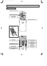
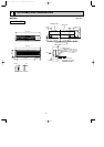
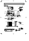
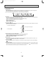
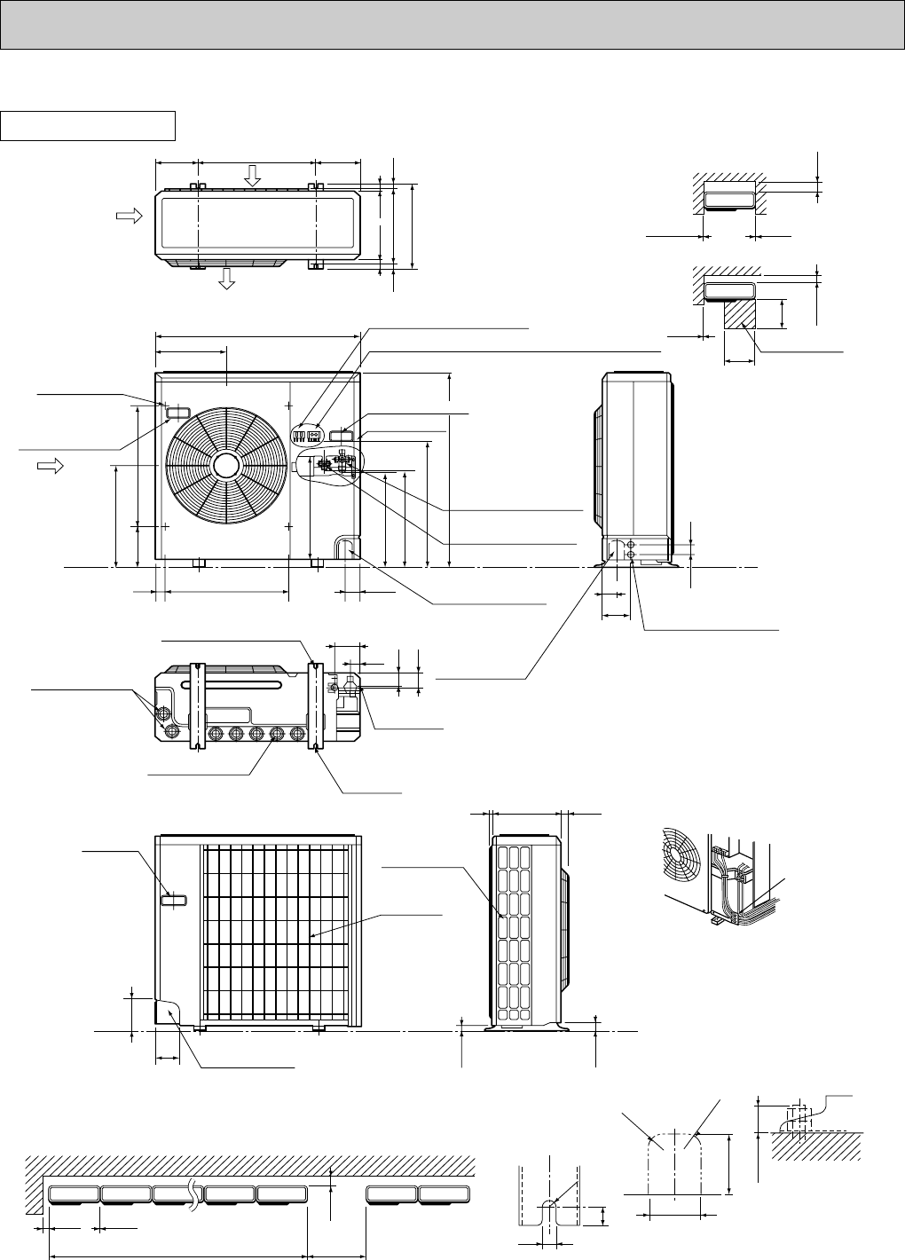
MU24WN
OUTDOOR UNIT
4
13/32
39-3/8
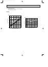
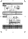
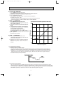
For 10 units or less
7-7/8
Outdoor Unit-Necessary surrounding clearance
(Concentrated installation)
The upper side must be open.
Outdoor Unit-Necessary surrounding clearance
7-7/8
13/32
13/32
13/32
Note:Allow adequate
upper clearance
5-29/32
19-11/16
19-11/16
Service space
Front opening
R13/16
R13/16
1 max.
Standard bolt length
2-9/16
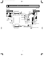
Front right piping holes-
detail figures
3-1/8
11/16
1/2
R1/4
15/16
1-5/16
Side air intake
9/32
15/16
11-5/8
Outlet guide
installation hole
11-7/8
Air intake
Air intake
Air outlet
34-1/4
7-9/32
7-9/32
19-11/16
13
14-1/4
11/16
9/16
1-9/16 1-1/16
Terminal block for indoor and outdoor unit connection
Terminal block for power line
Handle for moving
7-1/18 20-5/8
17-3/8
17-17/32
17-23/32
18-7/18
21-3/4
33-1/2
1-9/16
2-3/8
20-5/8
Service panel
Refrigerant-pipe flared
connection [5/8
Refrigerant-pipe flared
connection [3/8
Knock out hole
for front piping
(refrigerant,drainage
and wiring)
1-5/8
1-3/4
4-1/8
1-5/16
Bottom
piping hole
2-U-shaped
notched
holes
Drain hole [1-5/16
Drain hole [1-5/16
2-1/2o7/8 Oval holes
(standard bolt M10)
Handle for moving
A
Handle
for moving
5-7/16
3-3/4
Rear piping hole
Rear fresh
air intake
A
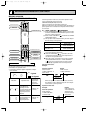
Knock out hole
for right piping
(refrigerant,drainage
and wiring)
4-3/4
1-3/4
2-1/16
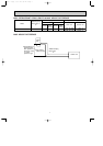
Knock out holes for
power line 2-[1-1/16
2-3/8
NOTE: Do not wire12V DC and
115V AC in same conduit hole.
Conduit hole
Unit: inch
OB311--1.qxp 04.1.13 9:53 AM Page 13