


15
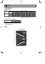
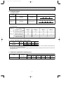
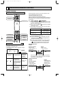
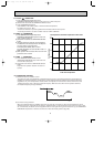
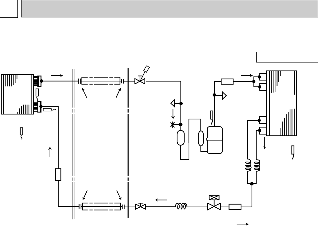
REFRIGERANT SYSTEM DIAGRAM
7
Indoor
heat
exchanger
Outdoor
heat
exchanger
Flared connection
Room temperature
thermistor
RT11
Indoor coil
thermistor
RT13(sub)
Discharge
temperature
thermistor
RT62
Flared connection
Stop valve
Stop valve
(with service port)
Capillary tube
O.D.0.14✕I.D.0.09✕1-31/32
Refrigerant flow in cooling
Compressor
Refrigerant pipe [5/8
(with heat insulator)
Refrigerant pipe [3/8
(with heat insulator)
Indoor coil
thermistor
RT12(main)
LEV
Strainer
Strainer
Accumulator
Ambient
temperature
thermistor
RT63
Strainer
#50
Capillary tube
O.D.0.16✕I.D.0.09✕7-7/8
(Upper path)
Capillary tube
O.D.0.16✕I.D.0.09✕3-15/16
(Lower path)
SERVICE
PORT
SERVICE
PORT
FUSIBLE
PLUG
#100
#100
MS24WN
INDOOR UNIT
OUTDOOR UNIT
MU24WN
Unit: inch
OB311--1.qxp 04.1.13 9:53 AM Page 15