


37
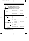
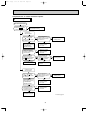
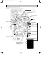
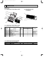
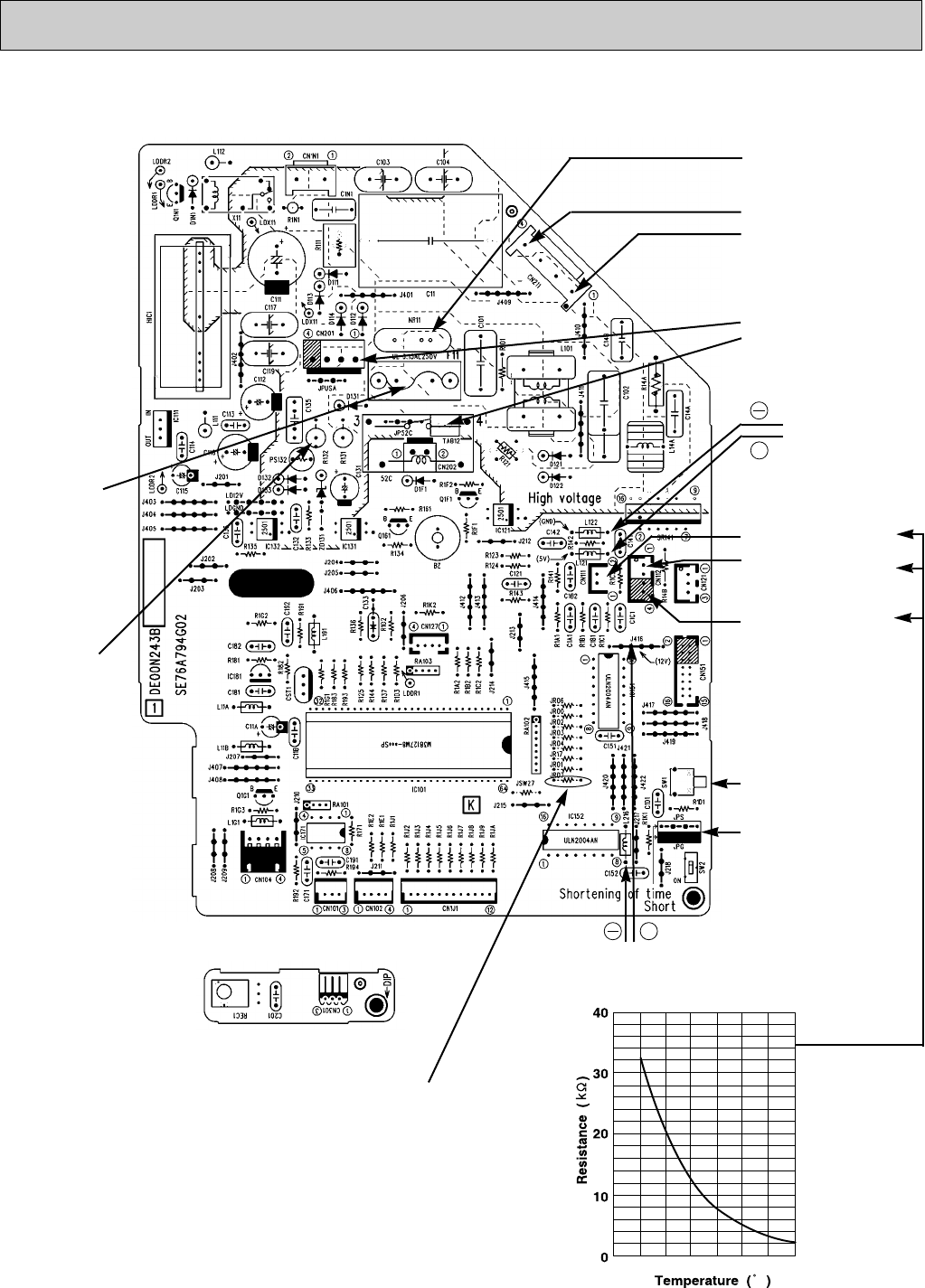
TEST POINT DIAGRAM AND VOLTAGE
MS24WN Indoor electronic control P.C. board
Fan motor power
supply
Fuse (F11)
250V AC 3.15A
}
Power supply input
115V AC
+
}
5V DC
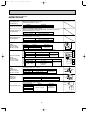
Indoor coil
thermistor(RT12(main))
Timer short mode point
(JPS, JPG)
(Refer to page 25.)
Emergency operation
switch
+
}
12V DC
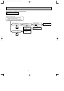
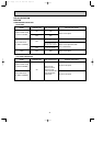
Indoor coil thermistor[RT12(main), RT13(sub)]
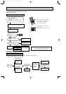
Room temperature thermistor (RT11)
32
F
50 68 86 104 122 140
Room temperature
thermistor(RT11)
Auto restart function
Solder the Jumper wire or the
Resistor 220Ω to the JR07.
(Refer to page 26.)
Indoor coil
thermistor(RT13(sub))
}
R132
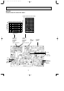
Receiver P.C. board
Varistor(NR11)
OB311--2.qxp 04.1.13 10:01 AM Page 37