


42
11-2. MU24WN
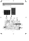
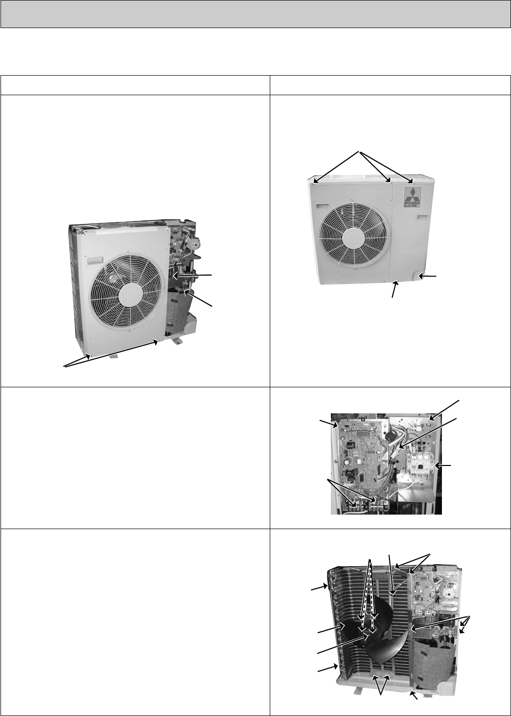
OUTDOOR UNIT
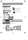
OPERATING PROCEDURE PHOTOS
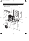
Photo 1
Photo 2
Photo 4
Photo 3
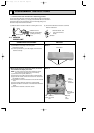
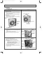
1. Removing the cabinet
(1) Remove the screws of the top panel and the top panel.
(2) Remove the screw of the service panel. To remove the
service panel, pull it down toward you and unhook the
catches on the both sides.
(3) Remove the screw of the cover panel. To remove the
cover panel.
(4) Remove the screws of the cabinet.
Open the cabinet to a 45-degree angle. Then lift it and
unhook the catches to remove.
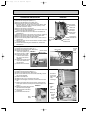
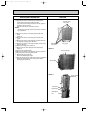
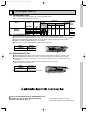
2. Removing the outdoor electronic control P.C. board
(1) Remove the top panel, the service panel and the cover
panel.
(2) Disconnect all the connectors and the terminals on the
outdoor electronic control P.C. board.
(3) Remove the outdoor electronic control P.C. board.
Cover panel
Screws of the top panel
Screw of the
service panel
Terminal
blocks
Compressor
contactor
Outdoor
electronic
control P.C.
board
Fan motor
connector
Relay
panel
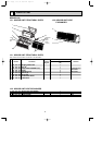
Propeller
nut
Screws of
the valve
bed
Screw of the
separator
support plate
Screws of the
motor support
Propeller
Screw of
the side
panel
Screw of
the side
panel
Screw of the separator
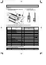
Screws
of the
fan motor
Lead
clamps
Screws of the cabinet
Discharge
pipe
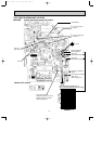
3. Removing the propeller and the outdoor fan motor
(1) Remove the cabinet. (Refer to 1.)
(2) Remove the propeller nut and the propeller.
NOTE:Loose the propeller in the rotating direction for
removal.
When attaching the propeller, align the mark on the
propeller and the motor shaft cut section.
Set the propeller in position by using the cut on the
shaft and the mark on the propeller.
(3) Remove the lead clamps and disconnect the outdoor
fan motor connector. (Photo 3)
(4) Remove the screws of the outdoor fan motor and the
outdoor fan motor.
Suction
pipe
OB311--2.qxp 04.1.13 10:02 AM Page 42