


8
RDV4136 Series Direct Vent Gas Fireplace
10010618
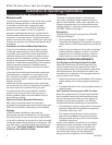
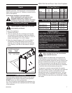
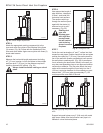
Installation: IN/IP Models
1. Thread the wiring through holes on the end panels
of appliance. Take care not to cut wire or insulation
on metal edges. Route the wire to a conveniently
located receptacle box.
2. Attach the wire to the ON/OFF switch and install the
switch into the receptacle box.
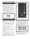
3. Connect the two (2) wires from wall switch to the
two (2) brown wires from the control module marked
SW1. Be sure to move the Remote/Off switch on the
control module to the OFF position. (Fig. 7)
NOTE: The remote does not work in this configu-
ration.
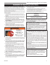
Always check for gas leaks with a mild
soap and water solution. Do not use an
open flame for leak testing.
The gas control is equipped with a captured screw type
pressure test point, therefore it is not necessary to pro-
vide a 1/8” test point up stream of the control.
When using copper or flex connector use only approved
fittings. Always provide a union when using black iron
pipe so that the gas line can be easily disconnected for
burner or fan servicing . See gas specifications for pres-
sure details and ratings.
The fireplace valve must not be subjected to any test
pressures exceeding 1/2 psi. Isolate or disconnect this
or any other gas appliance control from the gas line
when pressure testing.
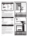
Remote ON/OFF Switch
FP297A
INSTA VENT FREE
UVHB26 GAS SUPPLY
7/1/98
FP297A
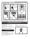
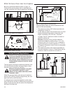
1/2” Gas Supply
1/2” NPT X 1/2” Flare Shut-off Valve
3/8” Flex line
(from valve)
Fig. 5 Typical gas supply installation.
FP1832
Fig. 7 Remote switch wiring for IN/IP models.
FP1832
Remote switch
3/08
Remote
Switch
SW1
SW1
Remote ON/OFF Switch
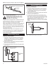
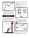
Installation: RN/RP Models
1. Thread the wiring through holes on the end panels
of appliance. Take care not to cut wire or insulation
on metal edges. Route the wire to a conveniently
located receptacle box.
2. Attach the wire to the ON/OFF switch and install the
switch into the receptacle box.
3. Connect the other ends of the wire to the gas control
valve. (Fig. 6)
TP
TH
TP
TH
FP1224
Remote switch
11/02
Remote ON/OFF
Switch or Thermostat
or Remote Control
Gas Control
Valve
FP1224
Fig. 6 Remote switch wiring diagram for RN/RP models.