26
RDV4136 Series Direct Vent Gas Fireplace
10010618
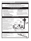
Lighting & Operating Instructions
For Fireplaces equipped with AF4000 Gas Valve
A. This fireplace is equipped with an ignition device
which automatically lights the pilot. DO NOT try to
light the pilot by hand.
B. BEFORE OPERATING, smell all around the
appliance area for gas. Be sure to smell next to
the floor because some gas is heavier than the
air and will settle on the floor.
What to do if you smell gas
• Do not try to light any appliance.
• Do not operate any electrical switch.
• Do not use any phone in your building.
For Your Safety, Read the Following Warnings
before Lighting the Appliance
• Immediately call your gas supplier from
a neighbor’s phone. Follow the gas
suppliers instructions.
• If you cannot contact your gas supplier call
the Fire Department
C. Do not use this appliance if any part has been
under water. Immediately call a qualified service
technician to inspect the appliance and replace
any part of the control system and any gas control
that has been under water.
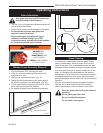
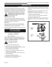
1. Turn the remote switch to the OFF position.
2. Turn OFF all electrical power to the fireplace if
service is required.
3. Open the lower access panel.
4. Turn the shut-off valve on the flexible gas line to
the OFF position.
FP297A
Warning: If you do not follow these instructions exactly, a fire or explosion may
result, causing property damage, personal injury and loss of life.
Lighting Instructions
Turning Off the Gas to the Appliance
FP297A
INSTA VENT FREE
UVHB26 GAS SUPPLY
7/1/98
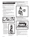
1. STOP! Read the safety information above before
continuing.
2. This appliance is equipped with an ignition device
which automatically lights the pilot. DO NOT try to
light the pilot by hand.
3. Access the gas control by removing the side cover
access door on the left side of the unit.
4. Turn the remote switch, if used, OFF. Turn the
wireless remote, if used, OFF.
5. Wait five (5) minutes to clear out any gas.
Then smell for gas, including near the floor.
If you smell gas, STOP. Follow instruction B
in the safety warnings above. If you do not
smell gas, go on to the next step.
6. Close the access door.
7. If the appliance will not operate, follow the
instructions TURNING OFF THE GAS TO
THE APPLIANCE, and call your service
technician or gas supplier.
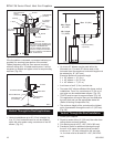
1/2” Gas Supply
1/2” NPT x 3/8” Flare
Shut-Off Valve
3/8” Flex Line
(From Valve)
Valve in the “ON” position
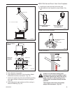
“S” Connection
Connect to Module
Spark to Pilot
Pilot Assembly
Pilot Gas Connection
Side or Back
“I” Connection
Connect to
Module
Main Valve Internal Solenoid
Connection
Green & White Wires
Outlet
Pressure Tap
Pilot Internal
Solenoid
Connection
Orange &
white Wires
Inlet Pressure
Tap
Pilot Adjustment
Screw


