


33
RDV4136 Series Direct Vent Gas Fireplace
10010618
Maintenance
Burner and Burner Compartment
It is important to keep the burner and the burner com-
partment clean. At least once per year the logs and lava
rock/ember material should be removed and the burner
compartment vacuumed and wiped out. Remove and
replace the logs as per the instructions in this manual.
Always handle the logs with care as they
are fragile and may also be hot if the fire-
place has been in use.
FK24/FK12 Fan Assembly
The fan unit requires periodic cleaning. At least once
per month in the operating season, open the lower lou-
vre panels and wipe or vacuum the area around the fan
to remove any build up of dust or lint.
Brass Trim
Clean the brass trim pieces using a soft cloth lightly
dampened with lemon oil. Do not use water or house-
hold cleaners on any brass components.
Contact your local representative to arrange an annual
service program.
Cleaning the Standing
Pilot Control System
The burner and control system consists of
• burner tube • gas orifice
• pilot assembly • thermopile
• millivolt gas valve
Most of these components may require only an oc-
casional checkup and cleaning and some may require
adjustment. If repair is necessary, it should be per-
formed by a qualified technician.
Logs May Be HOT!!
1. Turn off pilot light at gas valve side.
2. Let fireplace cool if it has been running.
3. Remove window frame assembly. (Refer to Window
Frame Assembly Removal section)
4. Remove logs and ember material.
5. Vacuum burner compartment especially around
orifice primary air openings.
6. Visually inspect pilot. Brush or blow away any dust
or lint accumulation.
7. Reinstall logs and ember material.
8. Ignite pilot - Refer to Lighting Instructions.
9. Reinstall window frame assembly.
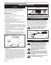
To obtain proper operation, it is imperative that the pilot
and burner’s flame characteristics are steady, not lifting
or floating.
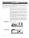
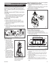
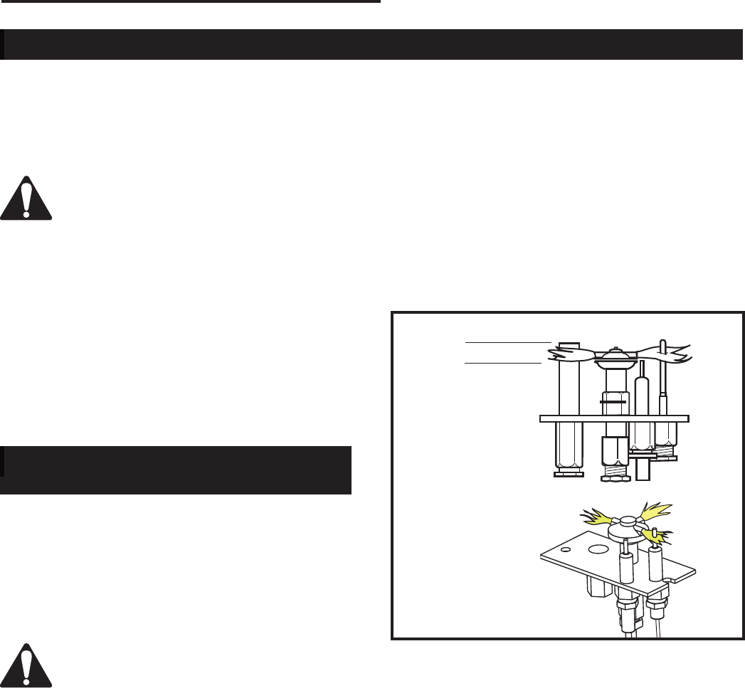
Typically, the top 3/8” or 1/2” of the thermopile should
be engulfed in the pilot flame. (Fig. 56)
To adjust pilot burner; (by qualified service technician)
1. Remove pilot adjustment cap.
2. Adjust pilot screw to provide properly sized flame.
3. Replace pilot adjustment cap.
The primary air shutter is set at factory and should only
be adjusted, if necessary, by a qualified service techni-
cian.
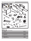
3/8” - 1/2”
(10 - 13 mm)
SIT Pilot
RN/RP
Fig. 56 Correct pilot flame appearance.
SIT Pilot
IN/IP