


13
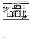
RDV4136 Series Direct Vent Gas Fireplace
10010618
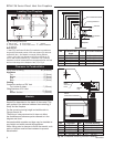
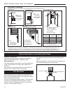
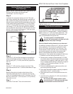
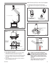
How to Use the Vent Graph
The vent chart should be read in conjunction with the
following vent installation instructions to determine the
relationship of the vertical and horizontal dimensions of
the vent system.
1. Determine the height of the center of the horizontal
vent pipe exiting through the outer wall. Using this
dimension on the Sidewall Vent Graph. (Fig. 13)
locate the point intersecting with the slanted graph
line.
2. From the point of this intersection, draw a vertical
line to the bottom of the graph.
3. Select the indicated dimension, and position the
fireplace in accordance with same.
Example A:
If the vertical dimension from the floor of the fireplace
is 11’ (3.4 m) the horizontal run to the face of the outer
wall must not exceed 14’ (4.3 m).
Example B:
If the vertical dimension from the floor of the unit is 7’
(2.14 m), the horizontal run to the face of the outer wall
must not exceed 8¹⁄₂’ (2.6 m).
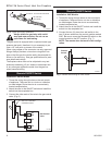
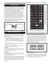
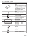
NOTE: The RDV4136 fireplace is shipped with a deflec-
tor behind the rear log support. If the fireplace is set up
with an extended vent configuration, it may be neces-
sary to loosen the two (2) screws securing the rear log
3
4
5
6
7
8
9
10
11
12
13
14
15
16
17
18
19
20
21
22
23
24
25
26
27
28
29
30
3 4 5 6 7 8 9 10 11 12 13 14 15 16 17 18 19 20
eg: A
eg: B
CFM102
DV Graphic
9/28/00 sta
Horizontal dimension from the outside face of the wall to
the center of the fireplace vent flange
Sidewall vent graph showing the relationship between vertical
and horizontal dimensions for a Direct Vent flue system.
Vertical dimension from the floor of the fireplace to
the center of the horizontal vent pipe
Fig. 13 Sidewall venting graph. (Dimensions in feet)
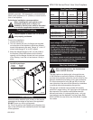
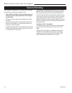
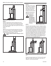
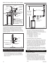
Twist Lock Pipes
When using CFM Corporation twist-lock pipe it is not
necessary to use sealant on the joints. The only areas
of the venting system that need to be sealed with high
temperature silicone sealant are the sliding joints of any
telescopic vent section used in the system.
To join the twist lock pipes together, simply align the
beads of the male end with the grooves of the female
end, then while bringing the ends together, twist the
pipe until the flange on the female end contacts the
external flange on the male end. It is recommended that
you secure the joints with three (3) sheet metal screws,
however this is not mandatory with twist lock pipe.
To make it easier to assemble the joints we suggest
putting a lubricant (Vaseline or similar) on the male end
of the twist lock pipe prior to assembly.
TWL100
Twist Lock Pipe
3/12/99 djt
Male End
Female End
Screw Holes
TWL100
Fig. 12 Twist-lock pipe joints.
support to the back of the fireplace and drop the deflec-
tor down over the air inlet ports. There are five (5) holes
on each side of the deflector. For extended vent runs,
hole ‘C’ works the best. (Fig. 14) This is a guide. It may
be necessary to adjust the deflector in a different hole
location depending on your installation. Be sure there is
no lifting or ghosting of the flame.
A
B
C
D
E
FP1833
deflector holes
3/08
FP1833
Fig. 14 Deflector holes.
In conjunction with the deflector over the air inlet, there
is a flue baffle. The baffle is shipped under the fireplace.
Remove the two (2) screws from the flue deflector and
secure the baffle to the deflector. (Fig. 15)